Lighting apparatus

a technology of light guide plate and light guide plate, which is applied in the direction of lighting and heating apparatus, planar/plate-like light guide plate, instruments, etc., can solve the problem that the requirement of exhibiting a particular pattern through the light guide plate is simply not satisfactory

Inactive Publication Date: 2015-03-05
LEXTAR ELECTRONICS CORP
View PDF1 Cites 0 Cited by
  • Summary
  • Abstract
  • Description
  • Claims
  • Application Information

AI Technical Summary

Benefits of technology

[0007]One aspect of the present invention is to provide a lighting

Problems solved by technology

Although the light can be uniformly distributed in view of the upper surface of the light guide plate, the

Method used


Image

  • Lighting apparatus
  • Lighting apparatus
  • Lighting apparatus

Examples


Embodiment Construction

[0018]Reference will now be made in detail to the present embodiments of the invention, examples of which are illustrated in the accompanying drawings. Wherever possible, the same reference numbers are used in the drawings and the description to refer to the same or like parts.

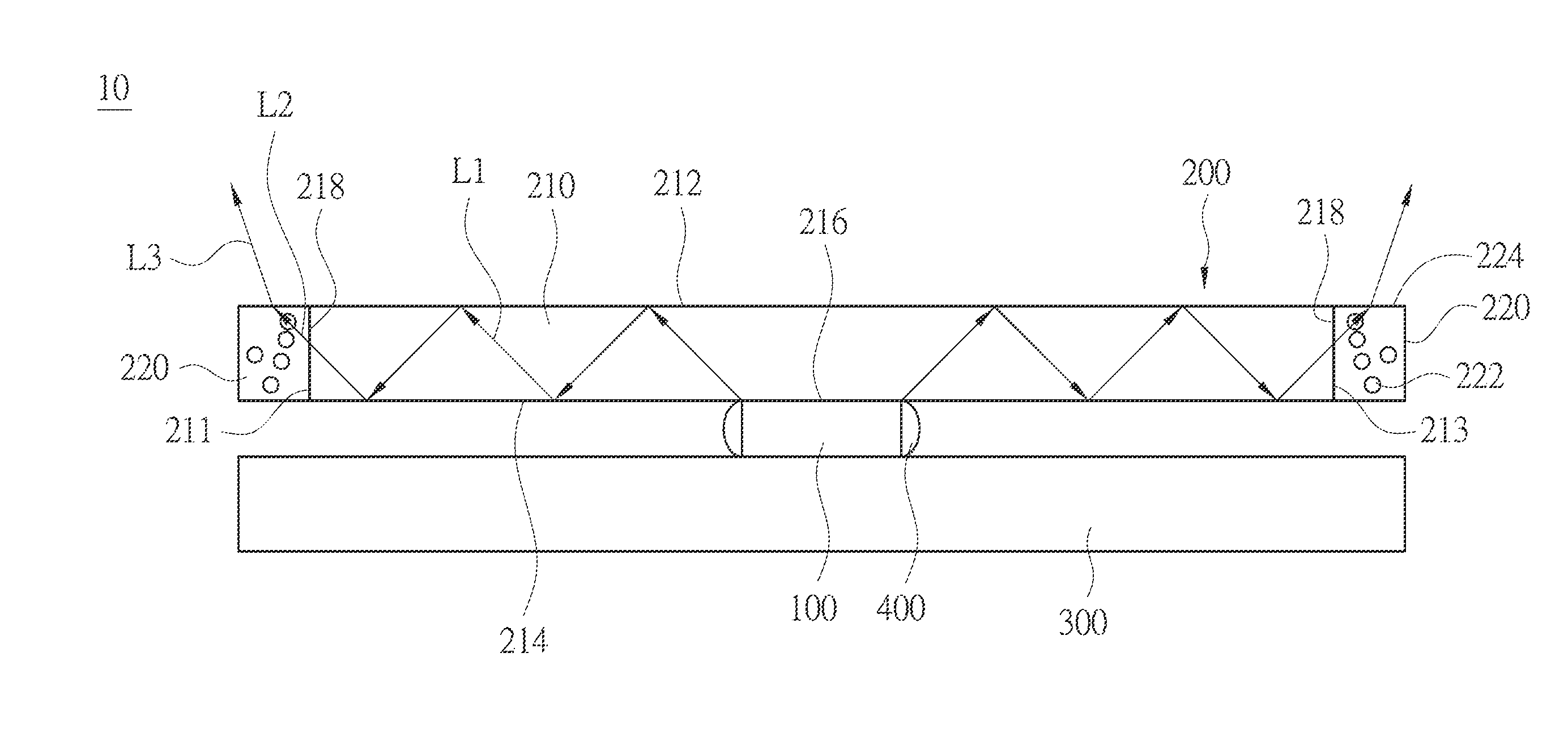
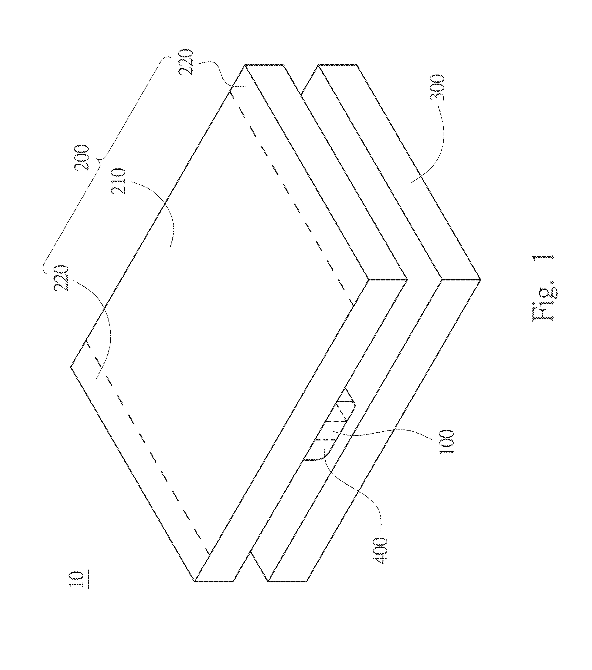
[0019]FIG. 1 is a perspective view of a lighting apparatus 10 in accordance with one embodiment of the present invention. As shown in FIG. 1, the lighting apparatus 10 includes at least one lighting element 100, a light guide plate 200 and a circuit board 300. The lighting element 100 is disposed between the light guide plate 200 and the circuit board 300. In other words, the light guide plate 200 is disposed above the lighting element 100, and the circuit board 300 is disposed under the lighting element 100.

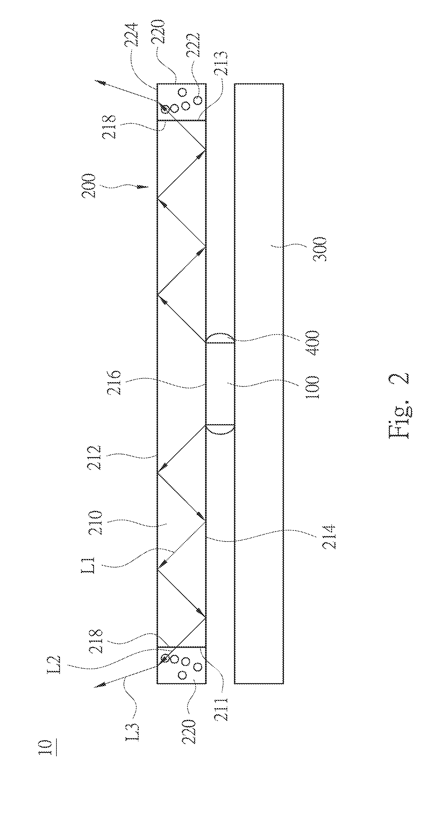
[0020]FIG. 2 is a side view of the lighting apparatus 10 in FIG. 1 illustrating the optical path thereof. As shown in FIG. 2, the light guide plate 200 includes an optical waveguide zone 210 and a waveleng...


PUM


Abstract

A lighting apparatus includes a lighting element and a light guide plate. The light guide plate includes an optical waveguide zone and a wavelength converting zone. The optical waveguide zone is disposed on the lighting element, and includes an upper total reflection surface, a lower total reflection surface, a light incident surface and a first light outgoing surface. The upper and lower total reflection surfaces are disposed on opposite sides of the optical waveguide zone. The light incident surface is positioned on a partial area of the lower total reflection surface, and positioned on the optical path of the light emitted by the lighting element. The first light outgoing surface connects the upper and lower total reflection surfaces. The wavelength converting zone is adjoined to the first light outgoing surface, and includes a wavelength converting material therein.

Description

RELATED APPLICATIONS[0001]This application claims priority to Taiwan Application Serial Number 102132039, filed Sep. 5, 2013, which is herein incorporated by reference.BACKGROUND[0002]1. Technical Field[0003]Embodiments of the present invention relates to a lighting apparatus.[0004]2. Description of Related Art[0005]Because a light emitting diodes (LED) has advantages such as low power-consumption, it has become a popular lighting device and been widely applied in illumination and backlighting of display. In order to increase the lighting range of the LED, a light guide plate is typically employed in which the LED can be disposed on the lateral surface of the light guide plate. When the LED emits light, the light enters the light guide plate through the lateral surface of the light guide plate, and it goes out of the light guide plate through the upper surface of the light guide plate.[0006]Although the light can be uniformly distributed in view of the upper surface of the light gui...

Claims


Application Information

Patent Timeline
IPC IPC(8): F21V8/00
CPCG02B6/0013G02B6/005G02B6/003G02B6/0041
Inventor LIN, CHING-YAO
Owner LEXTAR ELECTRONICS CORP
Why Eureka
Try Eureka