Eureka AIR delivers breakthrough ideas for toughest innovation challenges, trusted by R&D personnel around the world.

Turbine dental drill mechanism and turbine head with same mounted therein

a turbine head and dental drill technology, applied in dental tools, dental surgery, medical science, etc., can solve the problems of increased imbalance, poor components, and inconvenient use, so as to reduce the cost of high-precision machining, reduce noise, and reduce the cost

Inactive Publication Date: 2015-03-05
ZHENGZHOU ZEZHENG TECHN SERVICES
View PDF5 Cites 0 Cited by
  • Summary
  • Abstract
  • Description
  • Claims
  • Application Information

AI Technical Summary

Benefits of technology

The present invention solves the problem of high noise and imbalance in dental drills caused by the use of metal balls for automatic balancing. The use of sand grains, particularly metal sand grains, lowers the noise while correcting imbalance. A dynamic balancing body is also included in the wind wheel shaft to automatically adjust dynamic balance, even when there is a great degree of imbalance. This reduces the costs of high precision machining. Additionally, a cavity is formed between the rubber layer and the head cover to prevent teeth from touching the pressing part, which avoids impact on the rotation speed. Overall, the invention improves the performance and efficiency of dental drills.

Problems solved by technology

Such structures require a special tool to load and unload the bur, and this has proven inconvenient.
None of the above-described disposable dental drills has entered the stage of practical usage, for the reason that although China has several different factories producing disposable dental drills having an interference fit formed by an wind wheel shaft and a bur, the general accuracy of molds in China is 0.04 to 0.06 mm, and the accuracy for injection molded components is even poorer; in an environment of 300,000 revolutions per minute, therefore, the poor accuracy leads to imbalances, causing vibration and producing noise, which does not meet the standards, and they are not placed in practical use; the above-described two dental drills, in which pressure is used to load and unload the bur, have an even more complex structure, greater imbalance during rotation, and greater noise.

Method used


Image

  • Turbine dental drill mechanism and turbine head with same mounted therein
  • Turbine dental drill mechanism and turbine head with same mounted therein
  • Turbine dental drill mechanism and turbine head with same mounted therein

Examples


Embodiment Construction

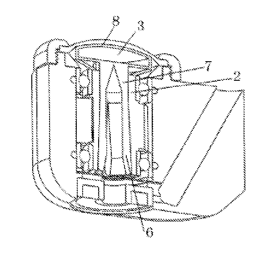
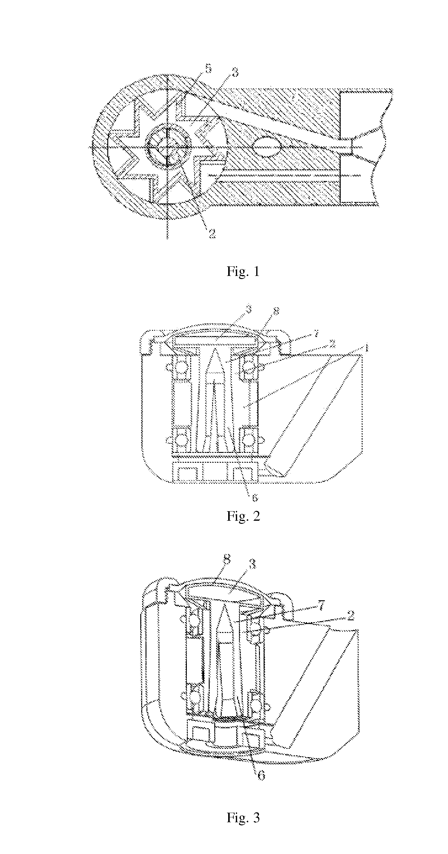
[0053]A turbine dental drill mechanism, comprising a turbine 1 and a turbine shaft 2, a balancing chamber 3 is provided on the mechanism, and an automatic balancing member is provided in the balancing chamber 3, wherein the balancing chamber 3 may be formed in the following ways.

[0054]One, the turbine 1 and the turbine blades 5 of the mechanism according to the present utility model are a hollow structure surrounding the turbine shaft 2, the hollow part is the balancing chamber 3, and an automatic balancing member is provided in the balancing chamber 3, as shown in FIG. 1.

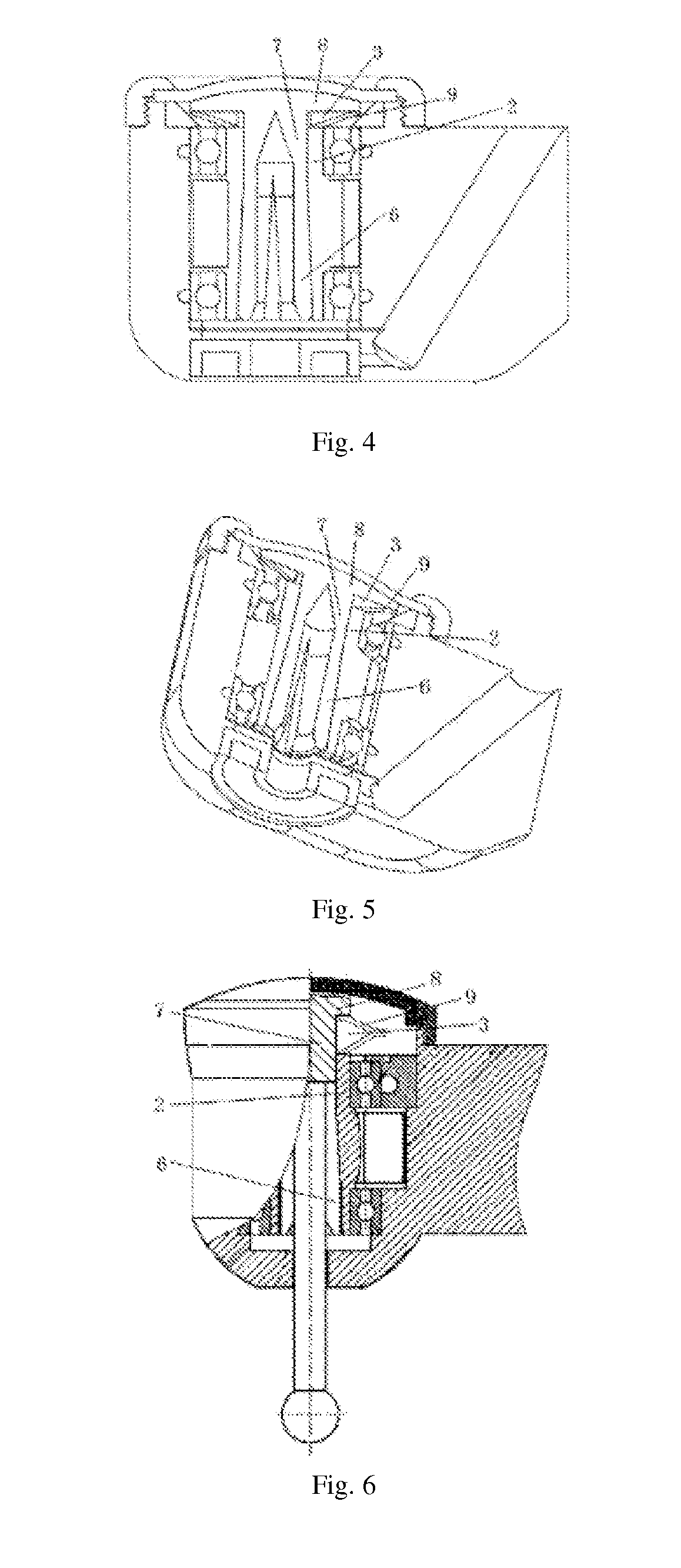
[0055]Two, a clamping jaw 6 is arranged inside the turbine shaft 2 of the mechanism, one end of the clamping jaw 6 is connected to a clamping jaw rod 7, the clamping jaw rod 7 extends out of a hole of the turbine shaft and is connected to a spring retaining board 8, the spring retaining board 8 and the end of the turbine shaft 2 are provided with a spring around the clamping jaw rod 7, the spring retaining board 8 ...


PUM


Abstract

A turbine dental drill mechanism, which includes a turbine and a turbine shaft. A balancing chamber is provided on the mechanism and includes an automatic balancing component provided therein. The automatic balancing component is a metal ball, sand grains or a flexible body. The metal ball in the balancing chamber can enhance the balance. The sand grains in the balancing chamber can reduce noise while also enhancing balance. The flexible body in the balancing chamber can eliminate noise and provide weight adjustment, thereby achieving automatic balancing.

Description

FIELD OF THE INVENTION[0001]The present invention relates to a major part used in dentistrydental drill, and in particular to the mechanism inside a turbine dental drill head and the movement of the turbine head with said mechanism mounted therein.DESCRIPTION OF THE PRIOR ART[0002]Generally speaking, a head for an air-type cutting device used in dentistry is provided with a head part at the top thereof, the required parts of a cutting tool are installed inside the head part, including a rotor shaft of the cutting tool, two bearings for supporting a rotation shaft, and an impeller arranged between the two bearing parts, such that the high-pressure air supplied via an air supply passage arranged in a handle part of the head impacts the impeller to rotate the cutting tool. Wind wheel shaft and blades according to the prior art are all integrally injection molded parts. For example, according to the Invention Patent No. 200520045733.3, its wind wheel shaft and bur act in concert throug...

Claims


Application Information

Patent Timeline
Patent Type & Authority Applications(United States)
IPC IPC(8): A61C1/05A61C3/02
CPCA61C3/02A61C1/05
Inventor LIU, XIAOXIA
Owner ZHENGZHOU ZEZHENG TECHN SERVICES
Why Eureka
Eureka Blog
Learn More