Systems, articles, and methods for stretchable printed circuit boards

a printed circuit board and stretchable technology, applied in the field of stretchable printed circuit boards, can solve the problems of insufficient application of rigid pcbs nor flexible pcbs, rendering the design of pcb b>100/b>, at best, unreliable, and at worst, insufficient for some applications

Active Publication Date: 2015-03-05
GOOGLE LLC
View PDF41 Cites 94 Cited by
  • Summary
  • Abstract
  • Description
  • Claims
  • Application Information

AI Technical Summary

Benefits of technology

[0016]A method of fabricating a stretchable printed circuit board may be summarized as including: depositing a first layer of stretchable dielectric material; depositing at least one conductive trace on the first layer of stretchable dielectric material, wherein the at least one conductive trace forms a serpentine signal path that extends along at least a portion of a length of the stretchable printed circuit board and includes a plurality of changes in direction across a width of the stretchable printed circuit board; depositing a second layer of stretchable dielectric material on the at least one conductive trace; and cutting away sections in the first and the second layers of stretchable dielectric material, each cut-away section positioned at an edge of the stretchable printed circuit board proximate at least one respective change in direction in the serpentine signal path. Depositing at least one conductive trace on the first layer of stretchable dielectric material may include: forming a flexible printed circuit board, wherein forming a flexible printed circuit board comprises: depositing a layer of polymer material; depositing a layer of conductive metal on the layer of polymer material; patterning the layer of conductive metal to provide at least one conductive trace having a serpentine signal path; and patterning the layer of polymer material; and depositing the flexible printed circuit board on the first layer of stretchable dielectric material. The polymer material may be selected from the group consisting of: a polyamide material, a polyimide material, and a polyamide-imide material.
[0017]A method of fabricating a stretchable printed circuit board may be summarized as including: fabricating a flexible printed circuit board, wherein fabricating a flexible printed circuit board comprises: depositing a layer of flexible dielectric material; depositing a layer of conductive metal on top of the flexible dielectric material; and etching a circuit pattern into the layer of conductive metal, wherein the circuit pattern includes at least one serpentine conductive trace that includes a plurality of changes in direction, removing at least some portions of the flexible dielectric material that are not covered by the at least one serpentine conductive trace; and enclosing at least a portion of the flexible printed circuit board in a stretchable dielectric material, wherein the stretchable dielectric material forms a crenulated shape that includes a plurality of crenulations across a length thereof, wherein each crenulation is positioned proximate and corresponds to a respective change in direction in the at least one serpentine conductive trace. Enclosing the flexible printed circuit board in a stretchable dielectric material may include: placing the flexible printed circuit board into a mold that provides a crenulated shape for the stretchable dielectric material; injecting the stretchable dielectric material, in liquid form, into the mold; solidifying the stretchable dielectric material; and removing the mold. Enclosing the flexible printed circuit board in a stretchable dielectric material may include: depositing a first layer of stretchable dielectric material; depositing the flexible printed circuit board on the first layer of stretchable dielectric material; depositing a second layer of stretchable dielectric material on the first layer of stretchable dielectric material, wherein the flexible printed circuit board is positioned in between the first and the second layers of stretchable dielectric material; and cutting away sections in the first and the second layers of stretchable dielectric material, each cut-away section positioned at an edge of the stretchable printed circuit board proximate at least one respective change in direction in the at least one serpentine conductive trace of the flexible printed circuit board.

Problems solved by technology

Flexible PCBs typically allow a degree of bendability, but neither rigid PCBs nor flexible PCBs can typically be stretched.
This limitation can render rigid PCBs and flexible PCBs inadequate for applications that impose stresses / strains on the PCB itself (e.g., where a PCB is used an electrical connector between two independently movable structures).
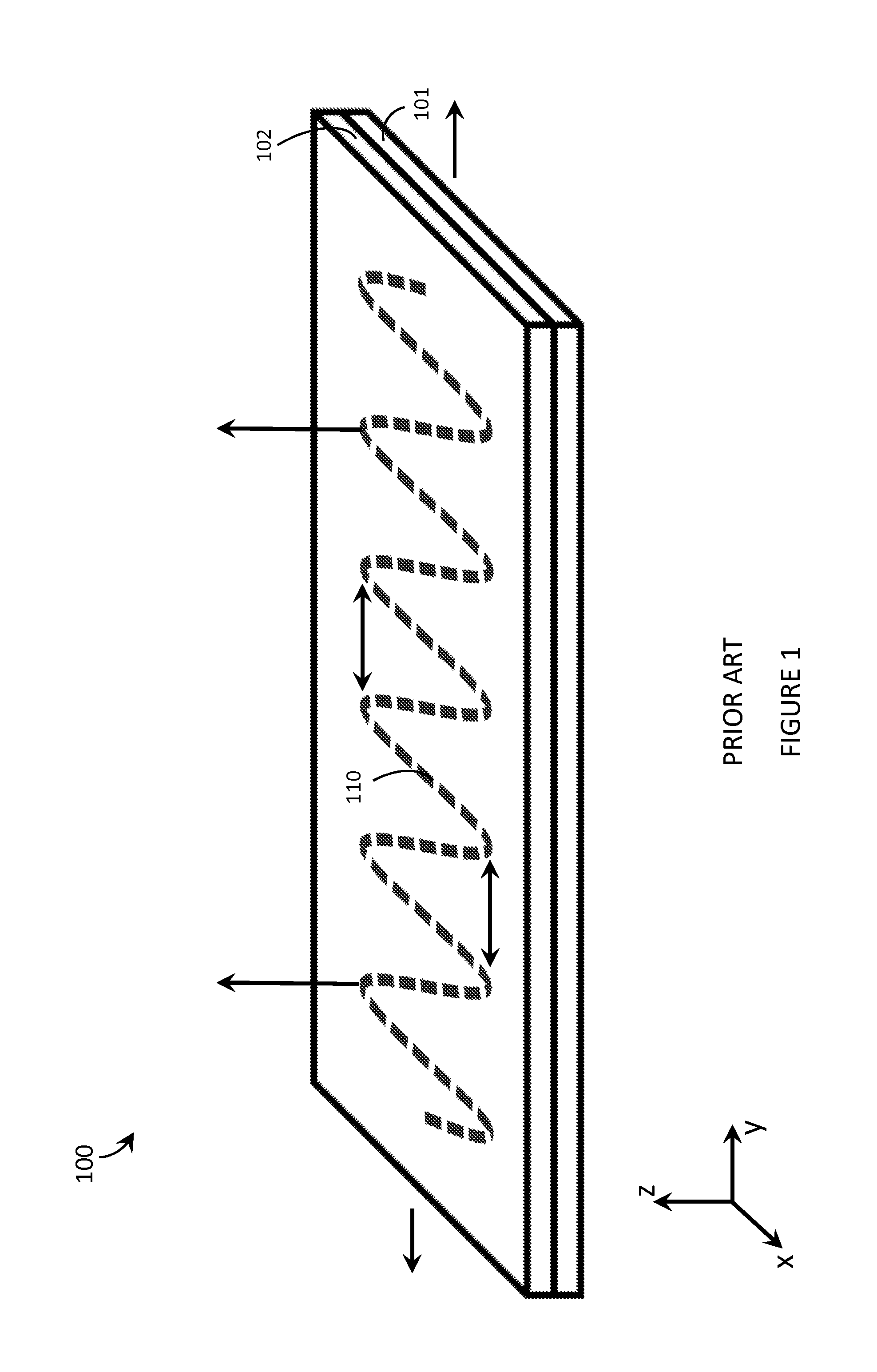
A drawback of the design of PCB 100 is that, when PCB 100 is stretched along the y-direction in the illustrated xy-plane, conductive trace 110 experiences a torsional force in the z-direction (represented in FIG. 1 by vertical arrows in the illustrated z-direction).
What is worse, the effect is aggravated by increasing the width and / or thickness of the dielectric layers 101, 102 (and / or by increasing the stretching, of course), rendering the design of PCB 100, at best, unreliable and, at worst, inadequate for some applications.
An example of an application for which this state of the art design for stretchable PCBs is inadequate is in wearable electronic devices.
However, the convenience of being able to carry a portable electronic device has also introduced the inconvenience of having one's hand(s) encumbered by the device itself.

Method used


Image

  • Systems, articles, and methods for stretchable printed circuit boards
  • Systems, articles, and methods for stretchable printed circuit boards
  • Systems, articles, and methods for stretchable printed circuit boards

Examples


Embodiment Construction

[0028]In the following description, certain specific details are set forth in order to provide a thorough understanding of various disclosed embodiments. However, one skilled in the relevant art will recognize that embodiments may be practiced without one or more of these specific details, or with other methods, components, materials, etc. In other instances, well-known structures associated with electronic devices, and in particular portable electronic devices such as wearable electronic devices, have not been shown or described in detail to avoid unnecessarily obscuring descriptions of the embodiments.

[0029]Unless the context requires otherwise, throughout the specification and claims which follow, the word “comprise” and variations thereof, such as, “comprises” and “comprising” are to be construed in an open, inclusive sense, that is as “including, but not limited to.”

[0030]Reference throughout this specification to “one embodiment” or “an embodiment” means that a particular feat...


PUM

PropertyMeasurementUnit
stretchableaaaaaaaaaa
lengthaaaaaaaaaa
widthaaaaaaaaaa

Abstract

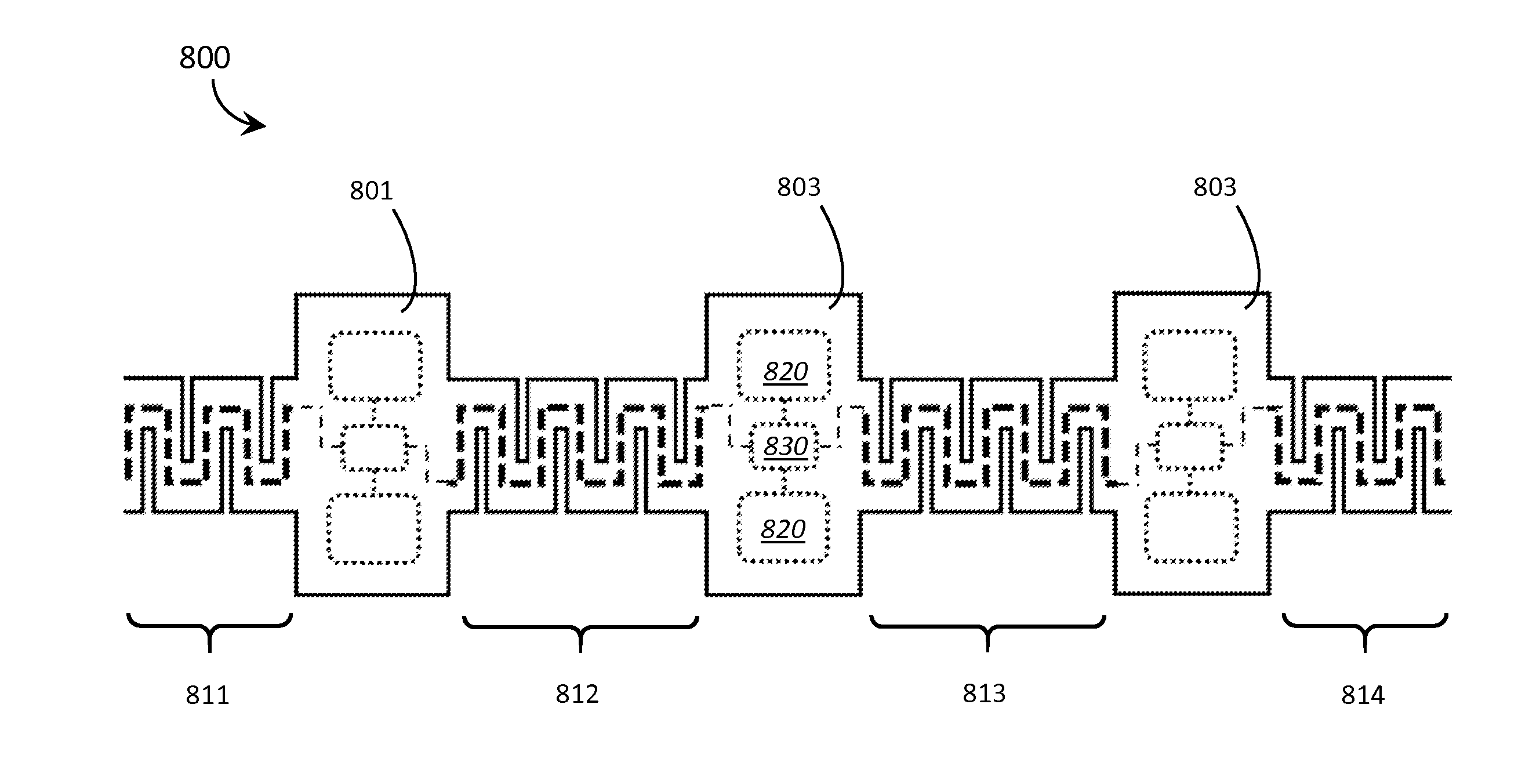
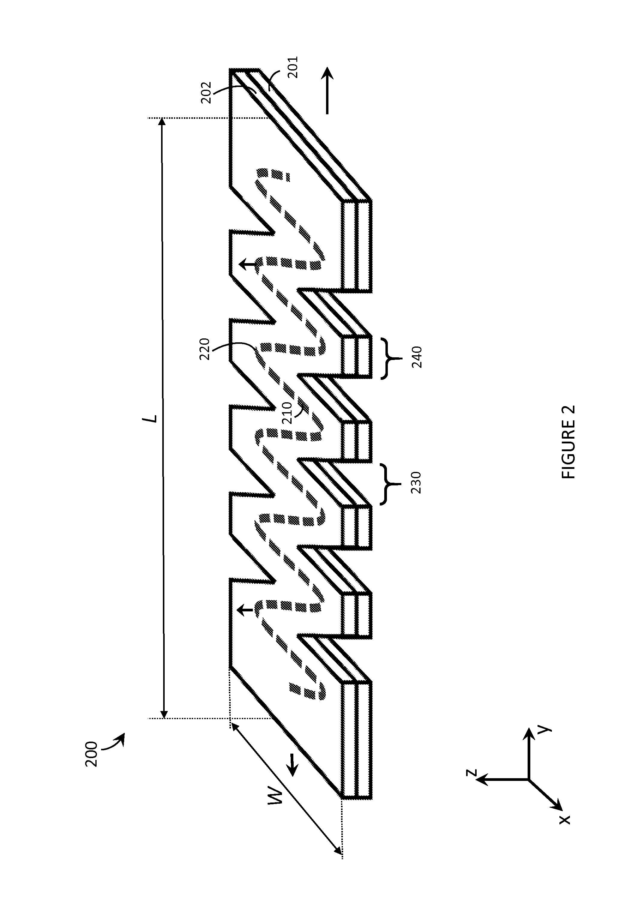
Improved stretchable printed circuit boards, and fabrication methods thereof, are described. The improved stretchable printed circuit boards include a serpentine conductive trace enclosed by stretchable dielectric material. The stretchable dielectric material has a serpentine shape itself, realized by crenulated edges. The crenulated edges reduce torsional strain on the conductive trace and are formed, for example, by cutting away sections of the stretchable dielectric material proximate segments of the serpentine conductive trace where the serpentine conductive trace changes direction.

Description

BACKGROUND[0001]1. Technical Field[0002]The present systems, articles, and methods generally relate to stretchable printed circuit boards and particularly relate to applications of stretchable printed circuit boards in wearable electronic devices.[0003]2. Description of the Related ArtStretchable Printed Circuit Boards[0004]Typical printed circuit boards (PCBs) are substantially planar structures formed of any number of layers of dielectric material with conductive traces carried thereupon or therebetween. The dielectric material (most commonly FR4, a composite material made up of fiberglass and epoxy resin) is typically rigid, though flexible PCBs have also been developed for some applications. Flexible PCBs typically allow a degree of bendability, but neither rigid PCBs nor flexible PCBs can typically be stretched. This limitation can render rigid PCBs and flexible PCBs inadequate for applications that impose stresses / strains on the PCB itself (e.g., where a PCB is used an electri...

Claims


Application Information

Patent Timeline
Patent Type & Authority Applications(United States)
IPC IPC(8): H05K1/03H05K3/00H05K3/06A61B5/0492A61B5/00A61B5/296
CPCH05K1/0393H05K1/0313A61B5/0492A61B5/681H05K2201/0154H05K3/0064H05K3/0014H05K3/0055H05K3/06A61B5/6828A61B5/6829A61B5/6802A61B5/6822A61B5/6823A61B5/6824A61B5/6826H05K1/0283H05K1/148H05K2201/09063H05K2201/09263A61B5/296
Inventor BAILEY, MATTHEW
Owner GOOGLE LLC
Why Eureka
Try Eureka