

Physical quantity sensor, vibratory device, electronic apparatus, and moving object
- Summary
- Abstract
- Description
- Claims
- Application Information
AI Technical Summary
Benefits of technology
Problems solved by technology
Method used
Image


Examples
first embodiment
[0049]Firstly, a physical quantity sensor according to the first embodiment will be explained.
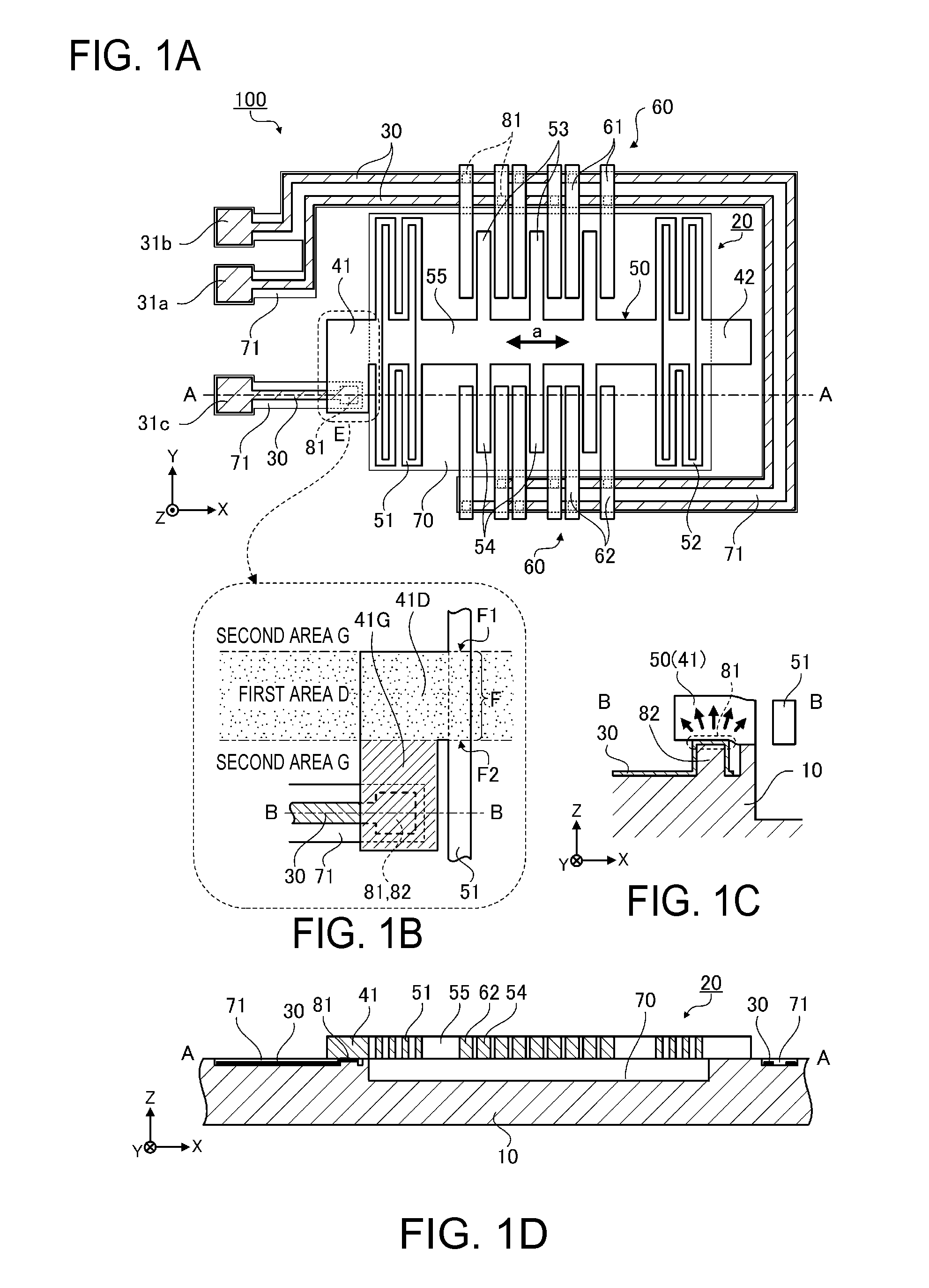
[0050]FIGS. 1A through 1D are schematic diagrams showing a physical quantity sensor 100 according to the first embodiment, wherein FIG. 1A is a plan view, FIG. 1B is an enlarged view of the E section shown in FIG. 1A, FIG. 1C is a cross-sectional view along the B-B line shown in FIG. 1B, and FIG. 1D is a cross-sectional view along the A-A line shown in FIG. 1A.
[0051]It should be noted that the explanation will hereinafter be presented assuming that in X, Y, and Z directions additionally described in the drawings, the X direction corresponds to the rightward direction, X-axis directions (the ±X directions) correspond to lateral directions, the Y direction corresponds to a depth direction, Y-axis directions (the ±Y directions) correspond to frontward and backward directions, the Z direction corresponds to an upper direction, and Z-axis directions (the ±Z direction) correspond to the upward an...
second embodiment
[0098]Next, a vibratory device according to a second embodiment will be explained. It should be noted that in the explanation, the constituents identical to those in the embodiment described above will be denoted with the same reference symbols, and any redundant explanation will be omitted.
[0099]FIGS. 3A and 3B are schematic diagrams showing a vibratory device 200 according to the second embodiment, wherein FIG. 3A is a perspective view, and FIG. 3B is a plan view.
[0100]While the movable electrode 50 is the movable electrode to be displaced in the X-axis directions in the embodiment 1, in the second embodiment, the movable electrode has a clamped-free beam structure in which the movable electrode is displaced or vibrates in the Z-axis directions.
[0101]The vibratory device 200 is a clamped-free beam type vibratory device, and is provided with a substrate 10V, a vibratory element 20V, a wiring line 30V, and so on.
[0102]The vibratory element 20V is provided with a fixation section 40V...
first modified example
[0133]In the first modified example shown in FIG. 7A, the fixation section 41 is further extended in the −X direction from the fixation section 41G in the second area G, and then further extended in the +Y direction to thereby form an area returned to the first area D, and the contact section 81 is disposed in the area.
[0134]According to the present modified example, although the contact section 81 is disposed in the first area D the same as the area where the fixation section 41D including the fixed support area F is disposed, the stress generated in the contact section 81 is not directly transmitted to the fixation section 41D, or is suppressed, and is transmitted to the fixation section 41D via the fixation section 41G, and is then further transmitted to the movable electrode 50. As a result, similarly to the first embodiment, it is possible to inhibit the stress applied to the movable electrode 50 from deforming the movable electrode 50, and from affecting the displacement of th...
PUM
 Abstract
Description
Claims
Application Information