Wind turbine transformer arrangement

a transformer arrangement and wind turbine technology, applied in the direction of mechanical equipment, electrical equipment construction details, machines/engines, etc., can solve the problems of transformer housing rupture and release pressure, transformer can present several negative effects, and transformers can be easily contaminated, so as to save the cost of an external crane, easy to be exchanged, and easy to reduce.

Active Publication Date: 2015-03-12
SIEMENS GAMESA RENEWABLE ENERGY AS
View PDF3 Cites 8 Cited by
  • Summary
  • Abstract
  • Description
  • Claims
  • Application Information

AI Technical Summary

Benefits of technology

[0020]Thus, the housing of the transformer may not experience high pressures. Thus, damage to the housing of the transformer may be avoided.
[0067]In addition, the safety of personnel working in the wind turbine may be increased.

Problems solved by technology

The electric arc can lead to a rapid local temperature increase that again leads to a vaporization of material, like oil, in the transformer.
This vaporization can lead to a pressure increase in the transformer that may cause the transformer housing to rupture and release the pressure.
The explosion of a transformer can present several negative effects, for example the transformer may be damaged and the oil present in the transformer may be released into the surrounding area.
When people are present in the surrounding of the transformer, an explosion can be a severe safety problem.
This presents further disadvantages in that the transformer still gets damaged due to the explosion of that the housing, which is very heavy and not very service friendly.
A malfunction can occur in the transformer.
A malfunction may lead to an electrical discharge in the transformer.
The electrical discharge may lead to an increase in the local temperature in the transformer.
The local increase in the temperature in the transformer may cause the oil to vaporize.
The vaporized oil may lead to a high increase in the pressure inside of the housing of the transformer.
Thus the housing of the transformer may stay undamaged after the increase of the pressure in the housing.
Oil may start to vaporize due to a malfunction in the transformer and increases of pressure in the transformer housing.
In addition to vaporized oil, liquid oil might also spill through the pressure release tube into the decompression chamber.

Method used


Image

  • Wind turbine transformer arrangement
  • Wind turbine transformer arrangement
  • Wind turbine transformer arrangement

Examples


Embodiment Construction

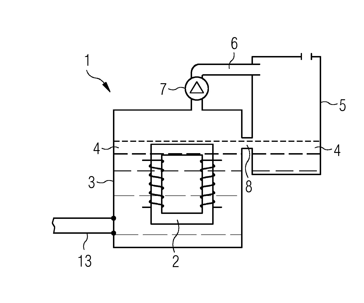
[0073]FIG. 1 shows a transformer arrangement 1 that comprises a transformer 2 that is arranged within a housing 3.

[0074]The housing 3 comprises oil 4 that is used as an insulation and cooling medium. The housing 3 comprises a connection 13 to connect the transformer arrangement 1 to a cooling circuit.

[0075]A decompression chamber 5 is connected to the housing 3 via a pressure release tube 6. The pressure in the housing 3 might increase rapidly due to a malfunction of the transformer 2. A malfunction of the transformer 2 could be an insulation problem that leads to sparking in the transformer. The sparking in the transformer leads to a vaporization of the oil 4 in the housing 3. The vaporization of the oil 4 in the housing 3 leads to an increase of the pressure in the housing 3.

[0076]If the housing 3 were a closed housing the rapid increase and the pressure within the housing would lead to a damage of the housing. In the transformer arrangement 1 the high pressure within the housing ...


PUM

PropertyMeasurementUnit
output voltageaaaaaaaaaa
pressureaaaaaaaaaa

Abstract

An improved transformer arrangement of a wind turbine is provided. A wind turbine transformer arrangement comprises a transformer that is arranged in the wind turbine. The transformer comprises a housing. The transformer housing is filled with an oil. The transformer arrangement comprises at least one decompression chamber and the interior of the transformer housing is connected to the interior of the decompression chamber by a pressure release tube in a way that an increase in the pressure in the transformer housing due to a malfunction of the transformer is transferred through the pressure release tube into the decompression chamber.

Description

CROSS-REFERENCE TO RELATED APPLICATIONS[0001]This application claims priority to EP Application No. 13184177.7, having a filing date of Sep. 12, 2013, the entire contents of which are hereby incorporated by reference.FIELD OF TECHNOLOGY[0002]The following relates to an improved transformer arrangement of a wind turbine.BACKGROUND[0003]A wind turbine commonly comprises a rotor, a nacelle and a tower. The rotor is typically attached so as to be rotatable to the nacelle and the nacelle is ordinarily arranged on top of the tower. An electric generator is usually connected to the nacelle of the wind turbine.[0004]The wind interacts with the rotor of the wind turbine and rotates the rotor. The rotation of the rotor is transferred to the electric generator where the rotational energy is transformed into electrical energy.[0005]The electrical energy of the generator is generally transformed by a transformer to a certain predetermined voltage level.[0006]It is therefore known to arrange a tr...

Claims


Application Information

Patent Timeline
Patent Type & Authority Applications(United States)
IPC IPC(8): H01F27/14H01F27/02H01F27/12
CPCH01F27/14H01F27/025H01F27/125F03D80/82Y02E10/72
Inventor GAARD, JESPERMUNK-HANSEN, THORKILNIELSEN, JACOB BLACHRASMUSSEN, CARSTEN K.
Owner SIEMENS GAMESA RENEWABLE ENERGY AS
Why Eureka
Try Eureka