
Vacuum

a vacuum and construction site technology, applied in the direction of vacuum cleaners, mechanical suction control, cleaning filter means, etc., can solve the problems of affecting performance, restricting airflow, and conventional vacuum systems that require regular cleaning or replacement of filters

Active Publication Date: 2015-03-19
BLACK & DECKER INC
View PDF7 Cites 11 Cited by
  • Summary
  • Abstract
  • Description
  • Claims
  • Application Information

AI Technical Summary

Benefits of technology

The present invention is a vacuum designed for construction projects that has a tank and a lid. It includes a separator plate that separates the motor chamber from the collection chamber, which houses a filter system. The airflow between the chambers is controlled by a valve assembly which can open or close conduits to selectively direct airflow. The vacuum can operate in two modes: the first mode filters the air and directs it towards the motor chamber, and the second mode redirects a portion of the filtered airflow back to the collection chamber to clean the filter system periodically. The technical effect of this invention is to provide a vacuum that can efficiently filter and direct airflow while also maintaining the filter system's performance through periodic cleaning.

Problems solved by technology

Over time, however, the debris accumulates on the filter, restricting airflow and hampering performance.
Consequently, conventional vacuum systems require regular cleaning or replacement of the filter.
This is a time-intensive process that interrupts workflow.

Method used


Image

  • Vacuum
  • Vacuum
  • Vacuum

Examples


Embodiment Construction

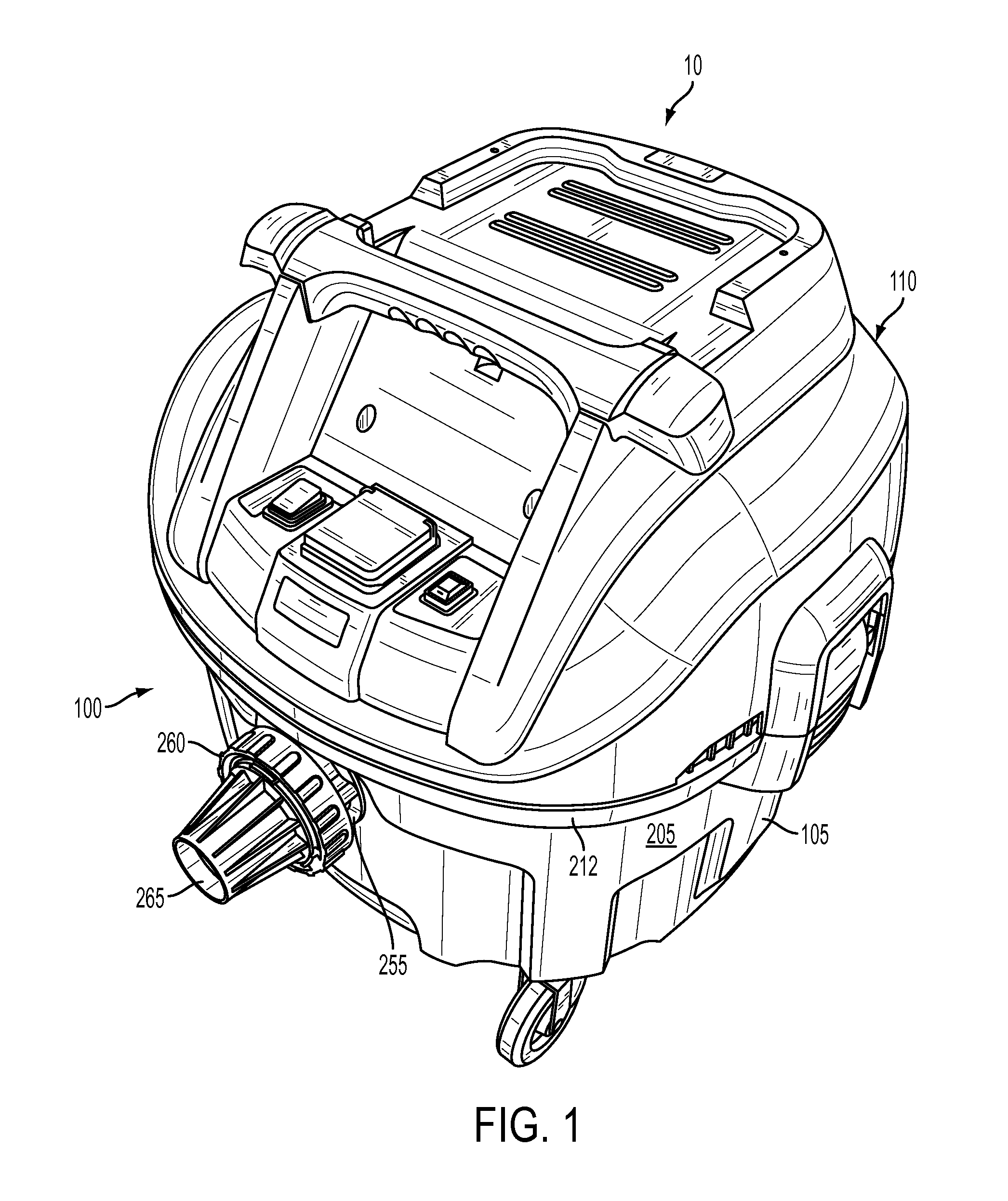
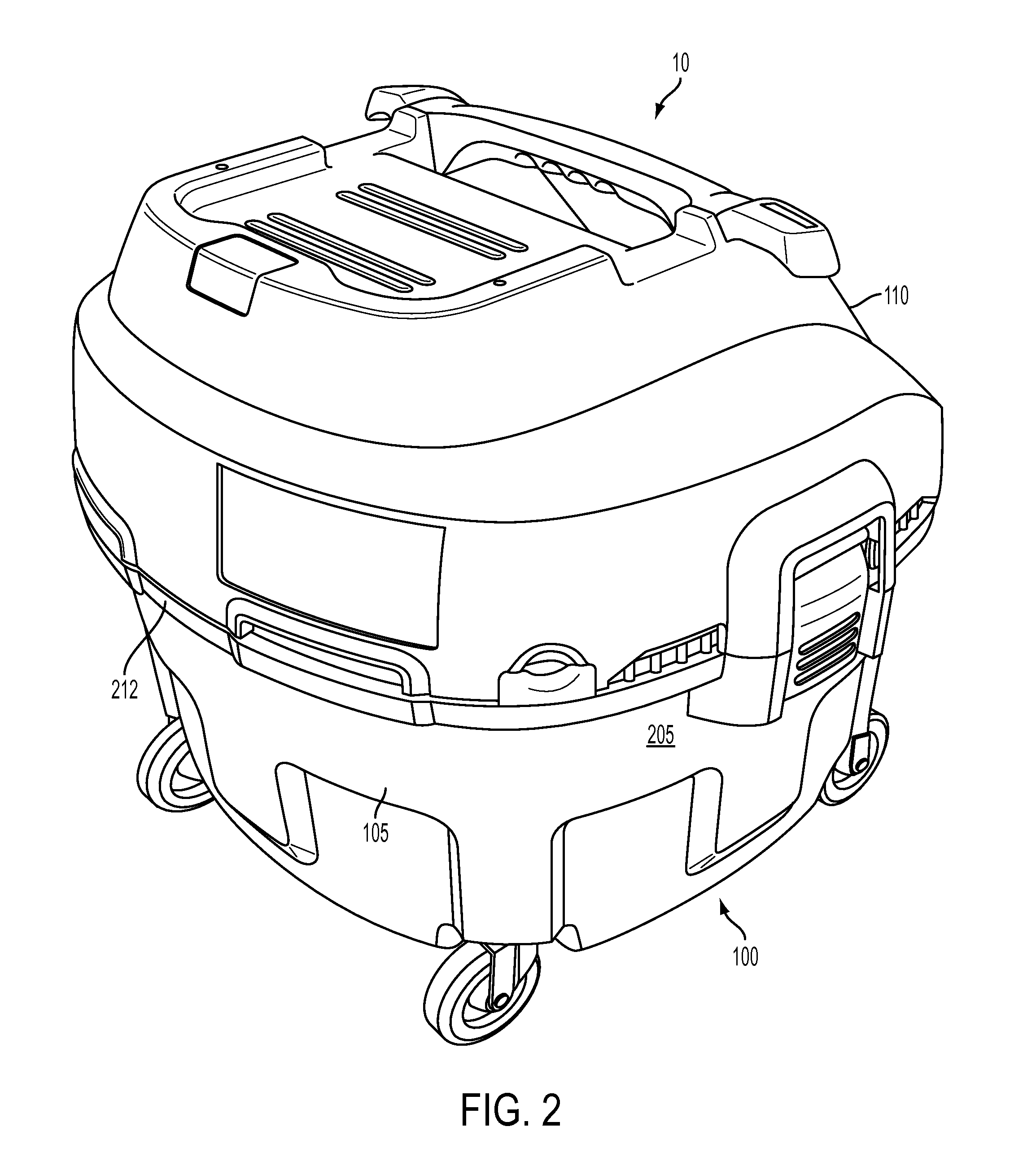
[0048]Referring to FIGS. 1 and 2, a vacuum system 10 in accordance with an embodiment of the invention (e.g., a wet / dry vacuum cleaner) includes a body 100 having a tank portion 105 coupled to a head or head 110 via one or more latch devices 112. Tank 105 may possess any dimensions and shapes suitable for its described purpose.

[0049]The tank portion 105 may further include one or more latch receptacles formed into the side wall 205. Each latch receptacle receives a corresponding latch device operable to couple the tank 105 to the head 110.

[0050]Referring to FIGS. 3 and 4, a vacuum supporting wheel assembly (e.g., rear wheels) may be in the form of a caster 305 including a wheel 315 disposed below a support structure 318. The wheel 315 is rotatably mounted to a fork 320 that, in turn, is pivotally coupled to the support 318 via a central pin 322. Support 318 includes an opening 316 for receiving pin 322 having an axis 319. Wheel 315 may rotate about axis 319 in opening 316 or it may ...


PUM


Abstract

The present invention is directed to a vacuum including a dust extraction system. The system includes a filter assembly, an airflow generation assembly, and valve assembly. The airflow generation assembly is configured to draw contaminated air toward the filter assembly and exhaust filtered air as a discharge stream. The filter assembly is configured to remove contaminants from the contaminated airflow by capturing particulate material suspended within the airflow. The valve assembly is configured to selectively direct filtered airflow into the filter assembly such that the filtered air stream cleans the filter.

Description

RELATED APPLICTIONS[0001]The present application is a continuation in part application of pending U.S. patent application Ser. No. 13 / 431,302, filed on Mar. 27, 2012 and entitled “VACUUM”, the contents of which is incorporated herein by reference in its entirety.FIELD OF THE INVENTION[0002]The present invention is directed toward a construction site or tool shop vacuum and, in particular, to a vacuum including a filter system and an airflow arrangement that periodically cleans the filter system during operation.BACKGROUND OF THE INVENTION[0003]Tool shop vacuum cleaners (e.g., wet-dry vacuums) are designed to collect debris from a work area or connected tool via suction. Such vacuums typically include a tank and motor that drives an impeller to generate an airstream within the tank. Since the airstream includes debris, care must be taken to prevent the debris from reaching the motor and causing damage. In light of this, conventional systems further include a filter positioned upstrea...

Claims


Application Information

Patent Timeline
IPC IPC(8): A47L5/36A47L9/10A47L9/30A47L7/00
CPCA47L5/365A47L9/30A47L9/106A47L7/0004A47L9/0072A47L5/362A47L7/0028A47L9/0036A47L9/009A47L7/0019A47L9/20A47L9/24
Inventor PLATO, BARRY E.BIANCO, JONATHANSANCHEZ, ABRAHAMCIESZKO, MICHAELMEREDITH, DARYL S.
Owner BLACK & DECKER INC
Learn More