Method and apparatus for filtering an air stream using an aqueous-froth together with nucleation

a technology of air stream and nucleation, which is applied in the direction of liquid separation agent, combination device, dispersed particle separation, etc., can solve the problem of air stream supersaturation, and achieve the effect of reducing relative humidity and increasing air volum

Inactive Publication Date: 2004-02-05
IND CLIMATE SOLUTIONS INC
View PDF9 Cites 25 Cited by
  • Summary
  • Abstract
  • Description
  • Claims
  • Application Information

AI Technical Summary

Benefits of technology

0061] The air stream shown at arrows 251 is exhausted through a condensing refrigerant coil 160 t

Problems solved by technology

In the "nucleation" technique, the incoming contaminated air stream is saturated wit

Method used


Image

  • Method and apparatus for filtering an air stream using an aqueous-froth together with nucleation
  • Method and apparatus for filtering an air stream using an aqueous-froth together with nucleation
  • Method and apparatus for filtering an air stream using an aqueous-froth together with nucleation

Examples


third embodiment

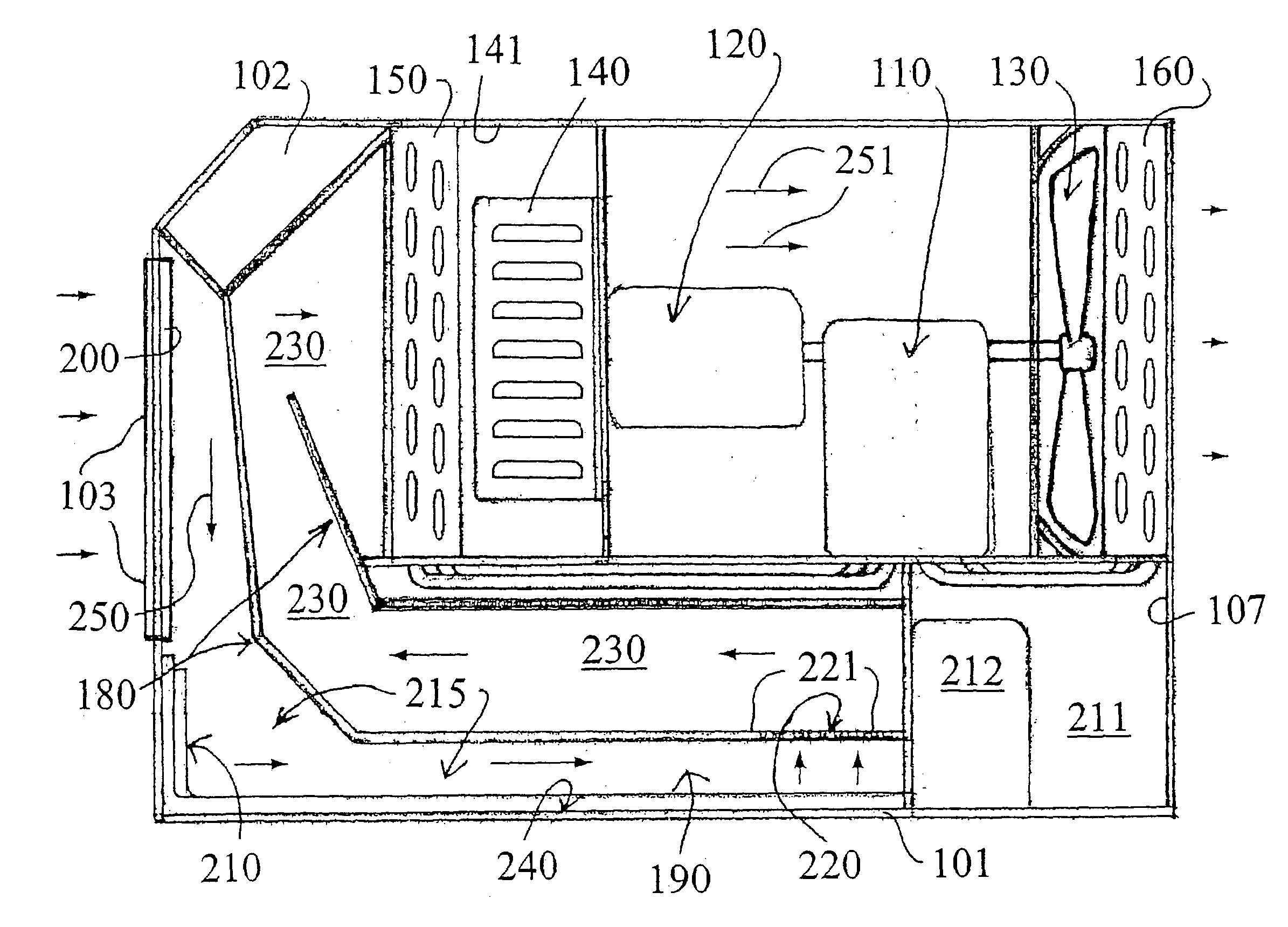
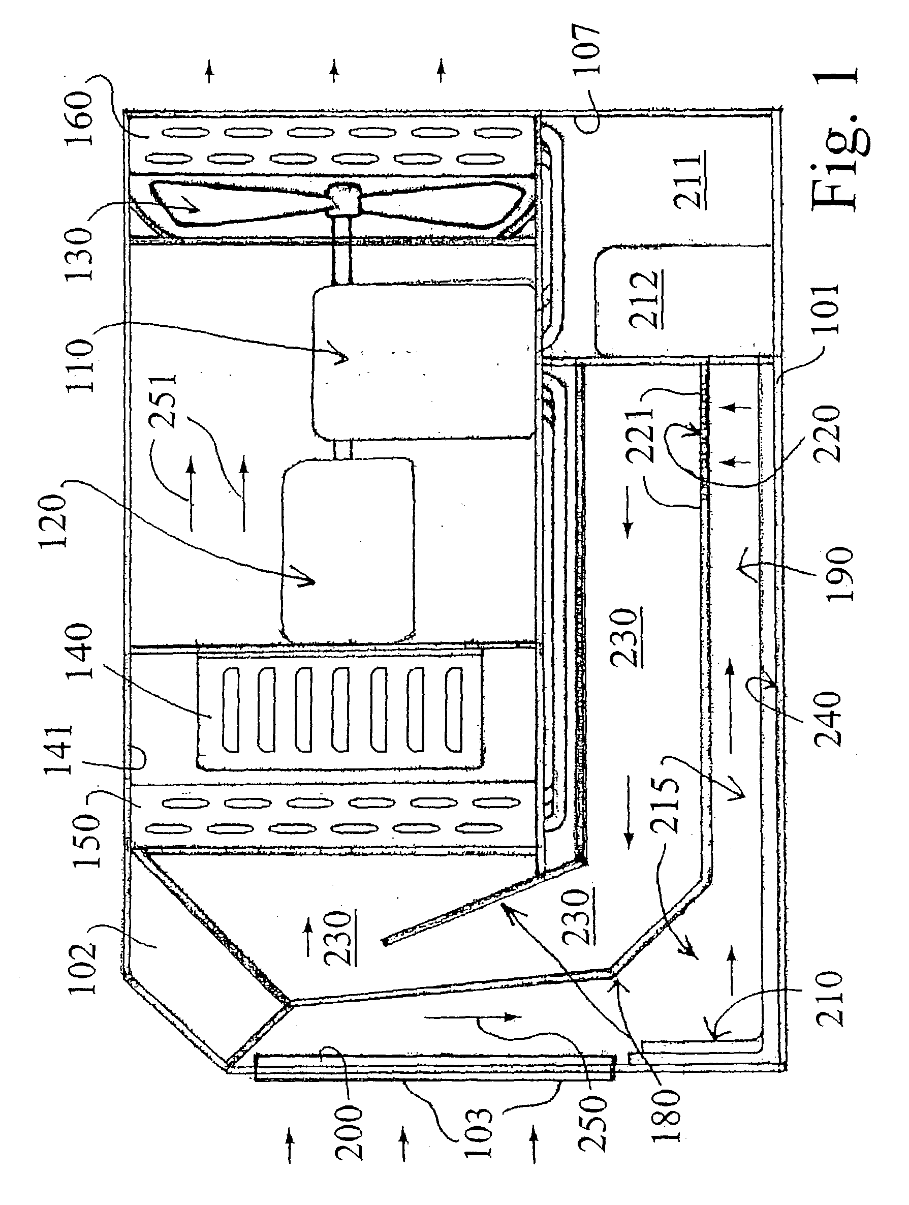
[0080] FIG. 7 illustrates a third embodiment shown generally as 800 wherein a contaminated air stream is represented by arrows 801 moving through an intake line shown as 802. A fogger nozzle system shown as 805 injects a fine mist 806 into the incoming contaminated air stream. The contaminated air stream moves downwardly as shown by arrow 807 into a liquid reservoir 808 having a liquid surface level 809. The contaminated air stream diffuses into the liquid reservoir as shown by arrows 811, causing the formation of aqueous-froth shown generally as 815. The bubbles in the aqueous froth contact cooling air and surfaces 820, causing the nucleated contaminants inside each bubble to contact the cool metallic surfaces 820. The large, condensed particles simply drain back into the liquid reservoir 808 to be decontaminated and / or disposed of.

fourth embodiment

[0081] FIG. 8 shows a fourth embodiment filter shown generally as 900 which includes the various stages of the filter arranged within a vertical and cylindrically shaped housing 910. The incoming contaminated air enters intake 920 and is forced downwardly into a liquid reservoir 930, wherein the upper surface of the liquid is shown as 931. An aqueous-froth is created immediately above the liquid surface 931 and a series of fogger nozzles 935 injects a fine mist into the incoming contaminated airstream. The bubbles of the froth move upwardly to a condensation stage shown generally as 950, when the bubbles are cooled, as described above, and the contaminants are coalesced onto cold, preferably metallic surfaces, or air and drained downwardly into the liquid reservoir 930. The decontaminated air stream 960 is pumped through a dewatering stage, typically by vacuum to an exhaust 970.

[0082] FIG. 9 is a schematic illustration representing how a mobile filter according to the present invent...

sixth embodiment

[0083] FIG. 10 is a schematic illustration of the invention. This embodiment illustrates a typical design of an industrial filter shown generally as 1300 and constructed in accordance with the present invention. Contaminated air enters intake 1310 and is forced downwardly into a liquid reservoir 1320 having a liquid surface level 1321. Fogger nozzles are not illustrated in the interest of clarity but are utilized to introduce a fine mist into the incoming airstream before the contaminated air is diffused into the liquid contained in reservoir 1320. The contaminated air stream enters the froth chamber 1330 wherein the contaminants are subjected to the nucleation described above, and are returned downwardly into the liquid reservoir 1320. The decontaminated air shown as 1350 is pumped through exhaust 1360. The contaminants are pumped from liquid reservoir 1320 into a disposal or reclamation tank 1370 by a liquid pump 1371. A liquid filter 1375 is utilized to remove as many solid conta...


PUM

PropertyMeasurementUnit
Angleaaaaaaaaaa
Sizeaaaaaaaaaa
Temperatureaaaaaaaaaa

Abstract

A method for urging contact between contaminants in an air stream and the wet surfaces of an aqueous-froth, and additional means of limiting the froth to a predetermined volume are provided. A wide spectrum of solution micro-droplet sizes (0.001 to 1000 micron) is introduced into a contaminated air stream. Micro-droplets suspended in the air stream remove contaminants by contact, collide and coalesce in the dynamics of the air stream and are removed by inertia. Smaller micro-droplets remain suspended in the air stream. The smallest micro-droplets evaporate, increasing the solution vapor pressure of the air stream. The humidified or saturated, contaminated air stream continuously expands the surface area of the solution reservoir exponentially into an aqueous froth of tiny bubbles. Airflow velocity drops in the micro-atmosphere inside each bubble of the froth. Contaminants and solution micro-droplets suspended in the air, inside the bubbles, settle out by the acceleration of gravity into the wet surfaces inside of each bubble. The froth is dewatered by condensation of the bubble walls, solution vapor, and micro-droplets, with trapped contaminants, onto the cold air, adjacent cold surfaces, and cold refrigerant coils. The liquid solution and contaminants drain from the refrigerant coils into the solution reservoir. Solution micro-droplets remaining in the air stream are drawn through a centrifugal blower/droplet separator and are thrown onto the blower housing to drain back into the solution reservoir. The air stream is passed through condensing refrigerant coils to reheat the air stream and reduce relative humidity. Variations including scaling, alternative methods of fogging, and additional applications are described.

Description

[0001] This application is a continuation-in-part of U.S. patent application Ser. No. 09 / 889,235 filed Jul. 10, 2001, and entitled, "Method and Means for Filtering an Air Stream with an Aqueous Froth." This application also claims the benefit of and priority from U.S. provisional application Serial No. 60 / 384,562 filed May 30, 2002.BACKGROUND--BRIEF SUMMARY OF THE INVENTION[0002] Generally, the invention of this application relates to filtering an air stream. Specifically, the invention relates to improvements to the technique of removing gaseous, liquid, and solid contaminants from an air stream with an aqueous-froth as described in parent application Ser. No. 09 / 889,225, incorporated herein by reference.[0003] The key aspect of the present invention is the novel combination of using "nucleation" in concert with an aqueous froth (shown best in FIGS. 3A-3G). In the "nucleation" technique, the incoming contaminated air stream is saturated with a fine mist produced by fogger nozzles, ...

Claims


Application Information

Patent Timeline
IPC IPC(8): B01D47/02B01D47/04B01D50/00
CPCB01D47/04B01D47/027B01D50/006B01D50/60
Inventor PELLEGRIN, ROY J.
Owner IND CLIMATE SOLUTIONS INC
Why Eureka
Try Eureka