
Smart FAIMS sensor

a sensor and sensor technology, applied in the field of smart faims sensors, can solve the problems of large sensor power relative to the sensor, mechanical pump use, and sensor bulkyness

Inactive Publication Date: 2008-01-24
OWLSTONE INC
View PDF11 Cites 22 Cited by
  • Summary
  • Abstract
  • Description
  • Claims
  • Application Information

AI Technical Summary

Benefits of technology

[0007]A smart FAIMS sensor system and method includes an array of two or more FAIMS sensors and a controller configured to independently control each of the FAIMS sensors in the array. In a preferred embodiment, the sensor array is normally operated with one FAIMS sensor operating in a high sensitivity mode while the remaining sensors are turned off. When the high sensitivity FAIMS sensor detects a possible event, each of the remaining sensors is turned on in sequence to confirm the possible event. Each of the remaining sensors is operated in a different selectivity mode that together forms a characteristic signature of a target analyte. The characteristic signature is more robust against false positives and an alarm is registered only when all remaining sensors confirm the possible event detected by the high sensitivity sensor.

Problems solved by technology

The use of a mechanical pump, however, has several disadvantages when FAIMS is used as a sensor.
The mechanical pump usually adds significant bulk to the sensor and requires large power relative to the sensor.

Method used


Image

  • Smart FAIMS sensor
  • Smart FAIMS sensor
  • Smart FAIMS sensor

Examples


Embodiment Construction

[0026]Preferred embodiments of the present invention include a FAIMS system such as the one described in PCT application numbers PCT / GB2005 / 050124 and PCT / GB2005 / 050126, referred to collectively as “Owlstone” and herein incorporated by reference in their entirety.

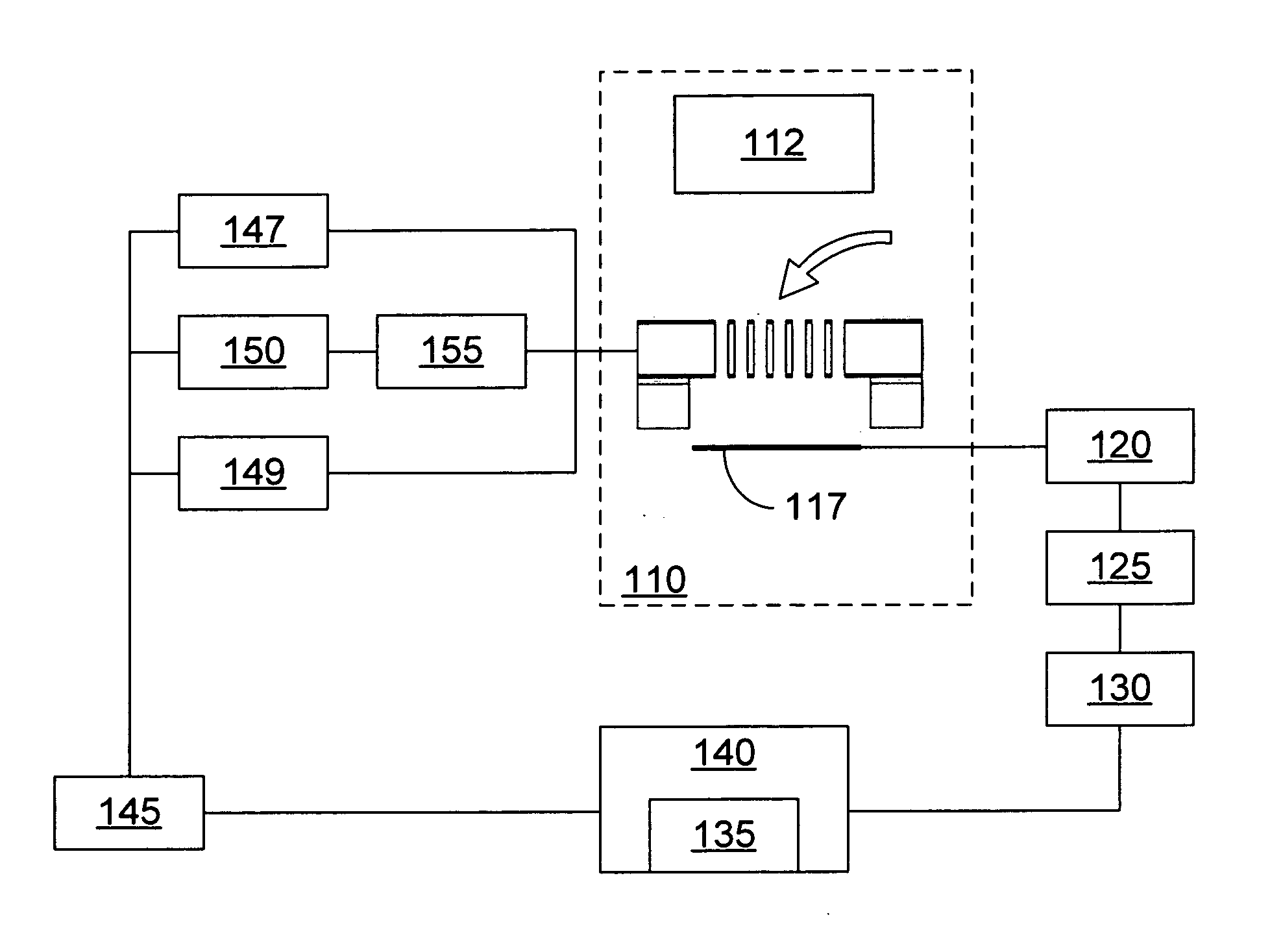
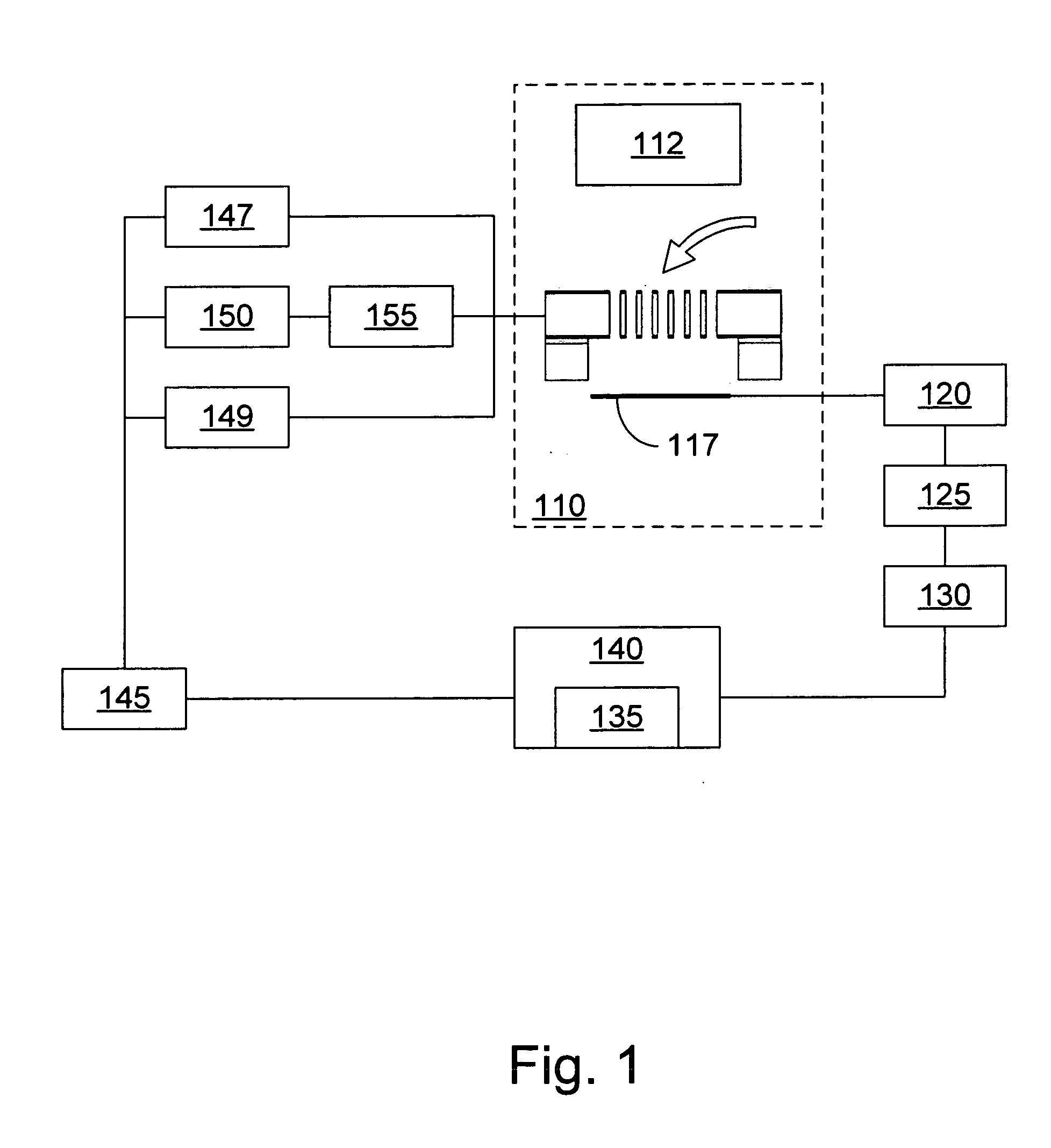
[0027]FIG. 1 is a block diagram of a smart FAIMS sensor 100 in one embodiment of the present invention. Sampling module 110 includes an ionization source 112 for ionizing molecules drawn into the sampling module and a filter 115 for separating the ions according to their mass and ionic mobility. Filtered ions are collected with a detection electrode 117. A low current amplifier 120, such as a transimpedence amplifier, for example, amplifies the signal from the detection electrode 117 and provides an amplified signal representing the detected ion current to an output DAQ 125. Additional signal processing may be performed on the amplified signal with a signal processing module 130.

[0028]A control module 140 receives the proce...


PUM


Abstract

There is no mask on the market or registered with the USPTO that uses ultraviolet light to kill air-borne viral and bacterial contaminants. The invention will ensure that if an individual must perforce be exposed to contaminated air as a result of natural or manmade events, then that individual will be able to use the Ultraviolet Light Assisted Protective Breathing Mask (the “ULAP Breathing Mask”) to kill whatever known or unknown viruses or bacteria may be in the vicinity. The ULAP Breathing Mask kills these contaminants before inhaled air ever reaches the filters. The prototype weighs approximately three pounds, and so is easily portable and is practical.

Description

BACKGROUND OF THE INVENTION[0001]The present invention relates to chemical / biological environmental sensors. More specifically, the invention relates to systems and methods for smart FAIMS sensors that dynamically change their operating point in response to their environment.[0002]Field Asymmetric Ion Mobility Spectroscopy (FAIMS) may be used to separate molecular or atomic ions based, in part, on the ions nonlinear ionic mobility in an electric field. In a typical FAIMS configuration, ions are directed between two plates that generate an electric field perpendicular to the flow direction of the ions. The electric field may be generated by applying a time varying voltage to the two plates. The time varying voltage is usually a superposition of two time varying signals or a superposition of a time varying signal and an adjustable constant signal.[0003]A first component of the time varying signal is an asymmetric oscillation wherein the peak magnitude of, for example, the positive por...

Claims


Application Information

Patent Timeline
Patent Type & Authority Applications(United States)
IPC IPC(8): H01J49/40
CPCG01N27/624
Inventor BOYLE, PAULRUSH, MARTYNRUIZ-ALONSO, DAVIDKOEHL, ANDREW H.PARRIS, RUSSELLWILKS, ASHLEY
Owner OWLSTONE INC
Learn More