Tunnel air-exchange device using a natural air-exchange method

A tunnel ventilation and natural ventilation technology, applied in mining equipment, heating methods, mechanical equipment, etc., can solve the problems of large power consumption, economic loss, and inability to discharge air to the outside, and achieve the effect of reducing economic loss and no power consumption

Inactive Publication Date: 2012-05-30
李学守
View PDF8 Cites 23 Cited by
  • Summary
  • Abstract
  • Description
  • Claims
  • Application Information

AI Technical Summary

Problems solved by technology

[0006] However, in the method of arranging multiple large exhaust fans at the top of the tunnel to discharge the air and dust inside the tunnel to the outside, sometimes the air inside the tunnel cannot be discharged to the outside even if the multiple exhaust fans are started at the same time.
[0007] That is, if the length of the tunnel is long, even if the exhaust fan exhausts the air inside the tunnel, the internal air can only move a limited distance and spread to the whole tunnel before reaching the next exhaust fan, causing the next exhaust fan to be unable to receive the previous exhaust fan The internal air sent is discharged to the outs

Method used


Image

  • Tunnel air-exchange device using a natural air-exchange method
  • Tunnel air-exchange device using a natural air-exchange method
  • Tunnel air-exchange device using a natural air-exchange method

Examples


Embodiment Construction

[0034] Embodiments of the present invention will be described in detail below with reference to the accompanying drawings.

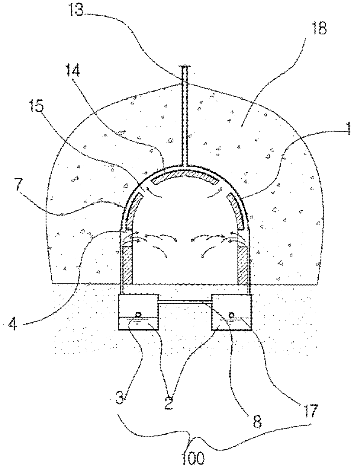
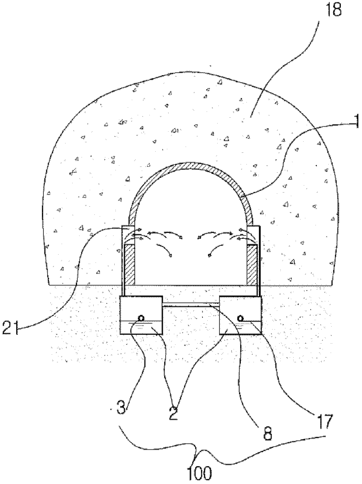
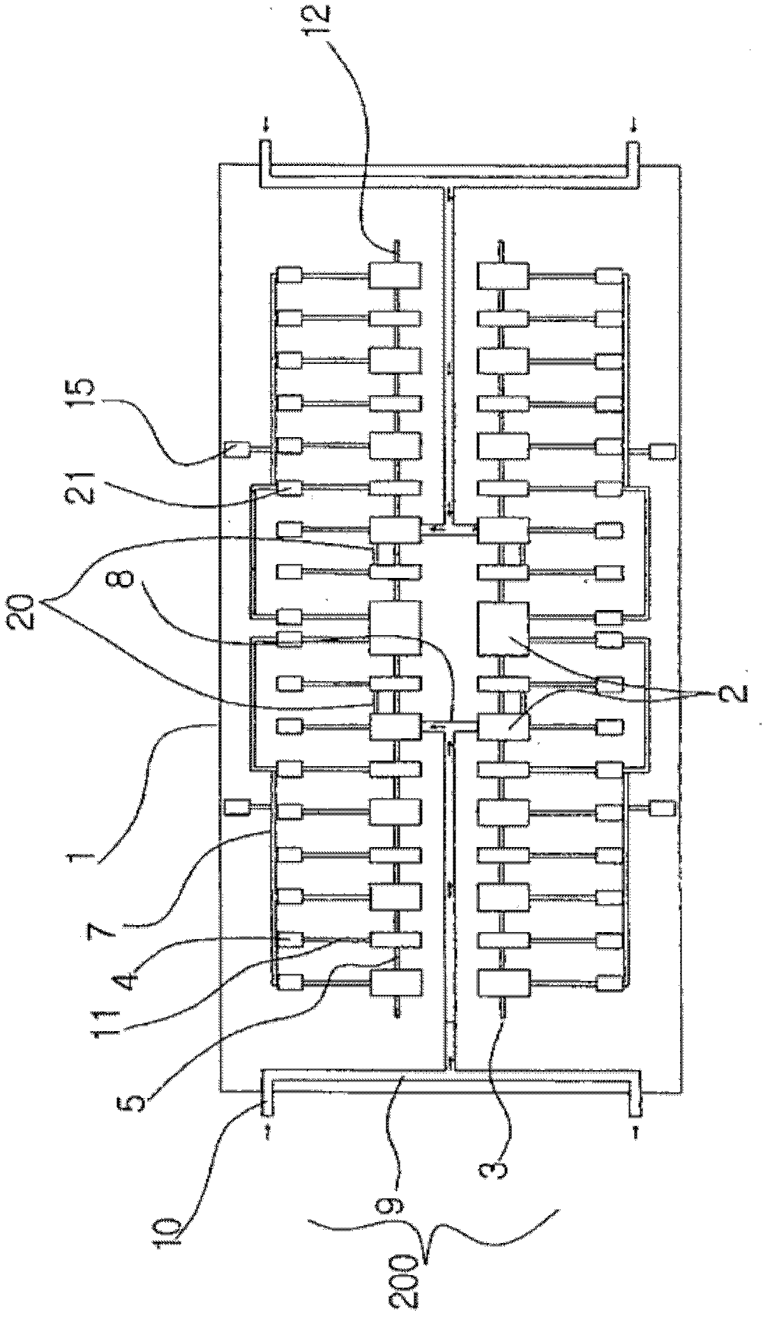
[0035] figure 1 is a front sectional view of the tunnel ventilation device of the present invention, figure 2 is a front sectional view of the air inlet in the tunnel ventilation device of the present invention, image 3 is a plan view of the tunnel ventilation device of the present invention, Image 6 It is a schematic diagram of the state when external air flows in through the air inflow pipe in the tunnel ventilation equipment of the present invention.

[0036] The tunnel ventilation device of the present invention combines the convection phenomenon and the chimney effect, can continuously supply fresh air to the inside of the tunnel 1 for circulation, and create a comfortable use environment.

[0037] The water storage tank suction device 100 included in the tunnel ventilation equipment divides the ground inside the tunnel 1 and continuously supp...


PUM


Abstract

The present invention relates to a tunnel air-exchange device, and more specifically to one in which: the air inside normal tunnels including tunnels through which vehicles run is cleaned and polluted internal tunnel air is expelled to the outside, to which end cold air, supplied to water tanks of different sizes provided in line at set intervals in the floor inside the tunnel, is used to ensure that the heavy soot and gases in the polluted hot air generated by vehicles, are sucked into the water tanks while the lighter foul air is discharged through chimneys by convection, thereby creating a pleasant tunnel environment by always maintaining clean air inside the tunnel; and which also extinguishes fires by spraying fire-extinguishing water during tunnel fires. Accordingly, the present invention combines a chimney effect with natural convection provided by the water tanks to exchange the air inside the tunnel and naturally expel polluted air, which is in contrast to exhaust fans of the prior art because there is no generation of noise or heat, and expenses can be reduced since there is no electrical consumption.

Description

technical field [0001] The present invention relates to a tunnel ventilation device, in particular to a tunnel ventilation device adopting a natural ventilation method, which can purify the air inside a general tunnel including a vehicle passage tunnel, and at the same time discharge the polluted air inside the tunnel to Outside, a row of multiple water storage tanks of different sizes are set at certain intervals on the ground inside the tunnel. The cold air generated by the water storage tanks is supplied to the inside of the tunnel and meets the hot polluted air generated by vehicles to generate convection, making it heavier The soot and exhaust gas are absorbed by the water storage tank, and the light polluting gas is discharged to the outside through the chimney, so that the air inside the tunnel is always fresh, creating a comfortable tunnel environment, and when a fire breaks out in the tunnel, firefighting water can be sprayed to carry out Extinguishing. Background t...

Claims


Application Information

Patent Timeline
IPC IPC(8): E21F1/00E21F1/18F24F8/133
CPCE21F3/00F24F2003/1617E21F1/18E21F1/003E21F5/00Y02A50/20F24F8/117F24F8/133A62C3/0221A62C31/02
Inventor 李学守禹钟镐金尚玉边宇坰
Owner 李学守
Why Eureka
Try Eureka