
Arrangement for a tank between a nacelle cowling and a turbomachine

a technology for turbomachines and nacelles, which is applied in the direction of machines/engines, power plant inspection panels, transportation and packaging, etc., can solve the problems of increasing the drag of the mass, the inability to integrate the liquid tank in the gear box, and the relative mass of the trapdoor used

Active Publication Date: 2015-03-19
SN DETUDE & DE CONSTR DE MOTEURS DAVIATION S N E C M A
View PDF5 Cites 28 Cited by
  • Summary
  • Abstract
  • Description
  • Claims
  • Application Information

AI Technical Summary

Benefits of technology

The patent describes a way to attach a tank directly to the inside of a panel, which is then fastened with the rest of the nacelle cowling. This results in a smaller unit that requires less space between the intermediate casing and the nacelle cowling. The technical effect is a more efficient and compact design that reduces the space required for the tank and its mounting.

Problems solved by technology

However, when the gear box is of larger dimensions, in particular for the driving of a large number of pieces of equipment of the turbomachine, it is not possible to integrate the tank of liquid in the gear box.
An increase in the main frame of the nacelle is thus obtained and consequently an increase in the drag of the mass.
However, the trapdoor used is relatively massive, as it has to be able to be manipulated frequently, and the system of articulation used, which generally comprises support elements arched as a “gooseneck” has a certain encumbrance.

Method used


Image

  • Arrangement for a tank between a nacelle cowling and a turbomachine
  • Arrangement for a tank between a nacelle cowling and a turbomachine
  • Arrangement for a tank between a nacelle cowling and a turbomachine

Examples


first embodiment

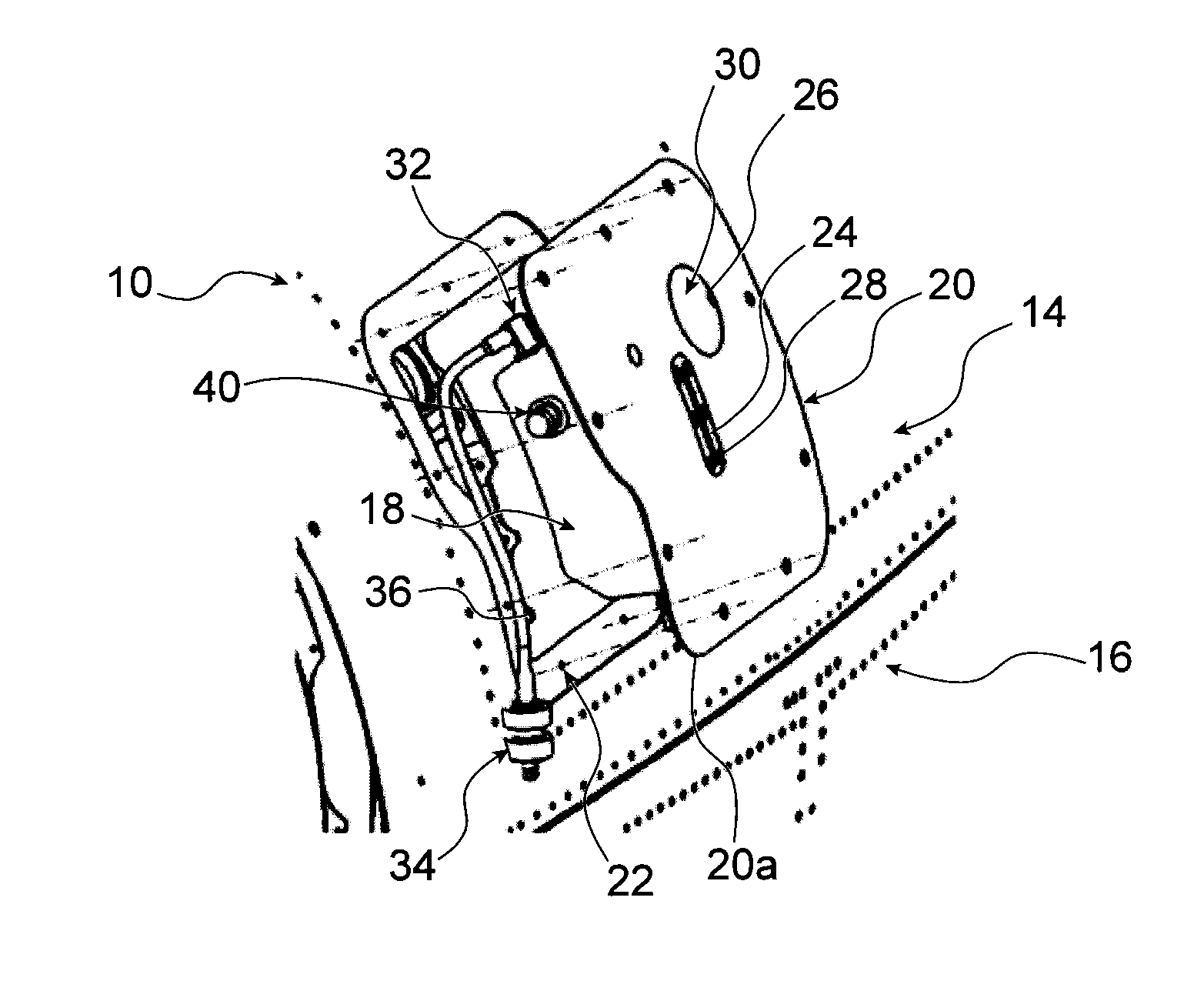
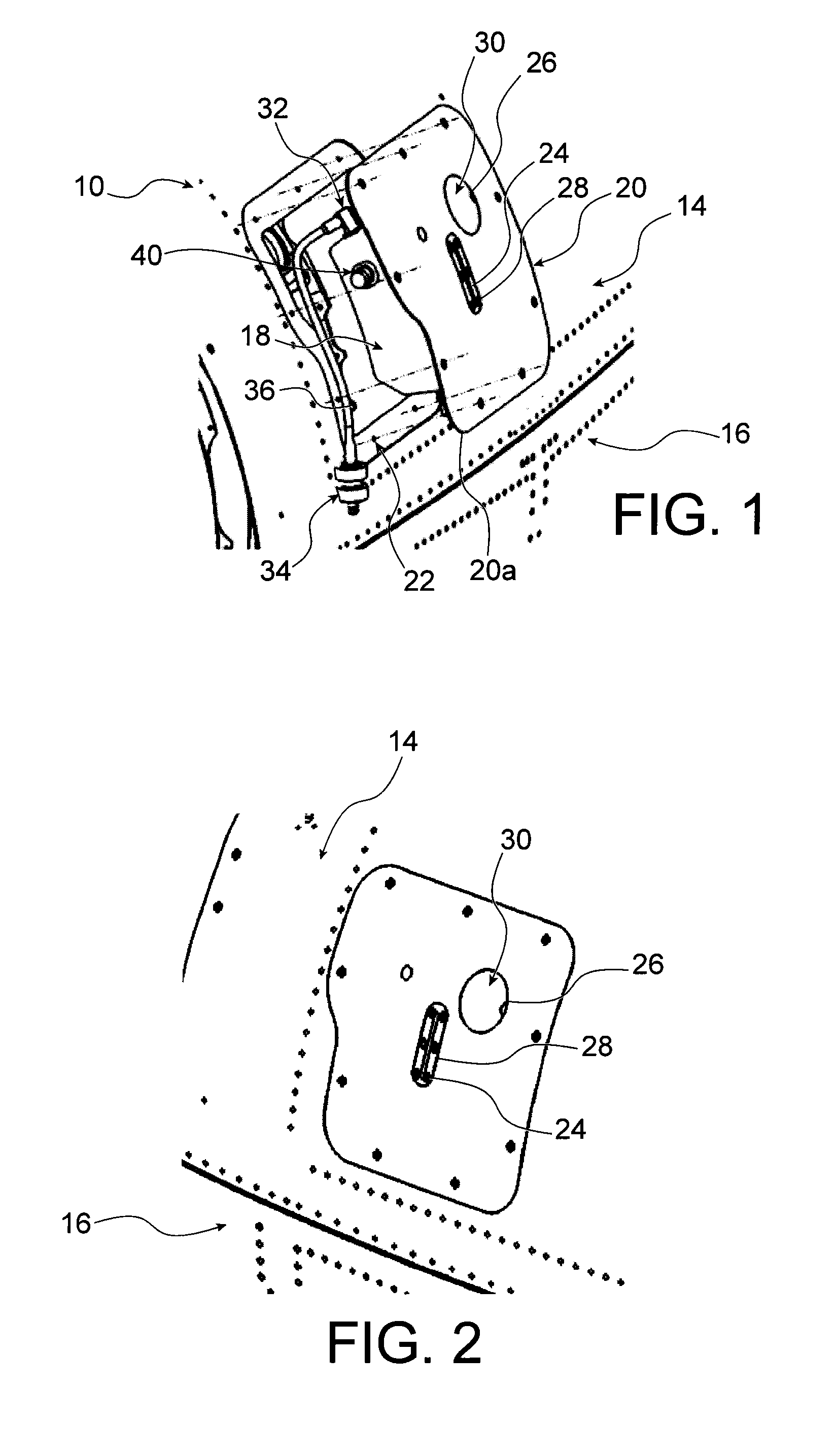
[0036]According to the invention, the tank 18 comprises a wall (not shown) which is placed side by side against the internal face 20a of the panel 20, with the tank 18 fastened to the internal face 20a of the panel 20 by any conventional means, for example by gluing.

second embodiment

[0037] the tank 18 and the panel 20 form an element of a single block, they are thus carried out as a single part.

third embodiment

[0038] the panel 20 constitutes a wall of the tank 18.

[0039]This makes it possible to suppress a space which may not be used between the tank 18 and the panel 20. This also makes it possible to easily transfer heat between the lubrication liquid contained in the tank 18 and the exterior of the panel 20, in order to cool it effectively.

[0040]Indeed, when the turbomachine 12 is an aircraft turbomachine, the panel 20 is in contact with air of which the temperature is about −50° C. The panel 20 as such forms a surface cooling device. Furthermore, this method of cooling is passive and does not require any supply of energy.

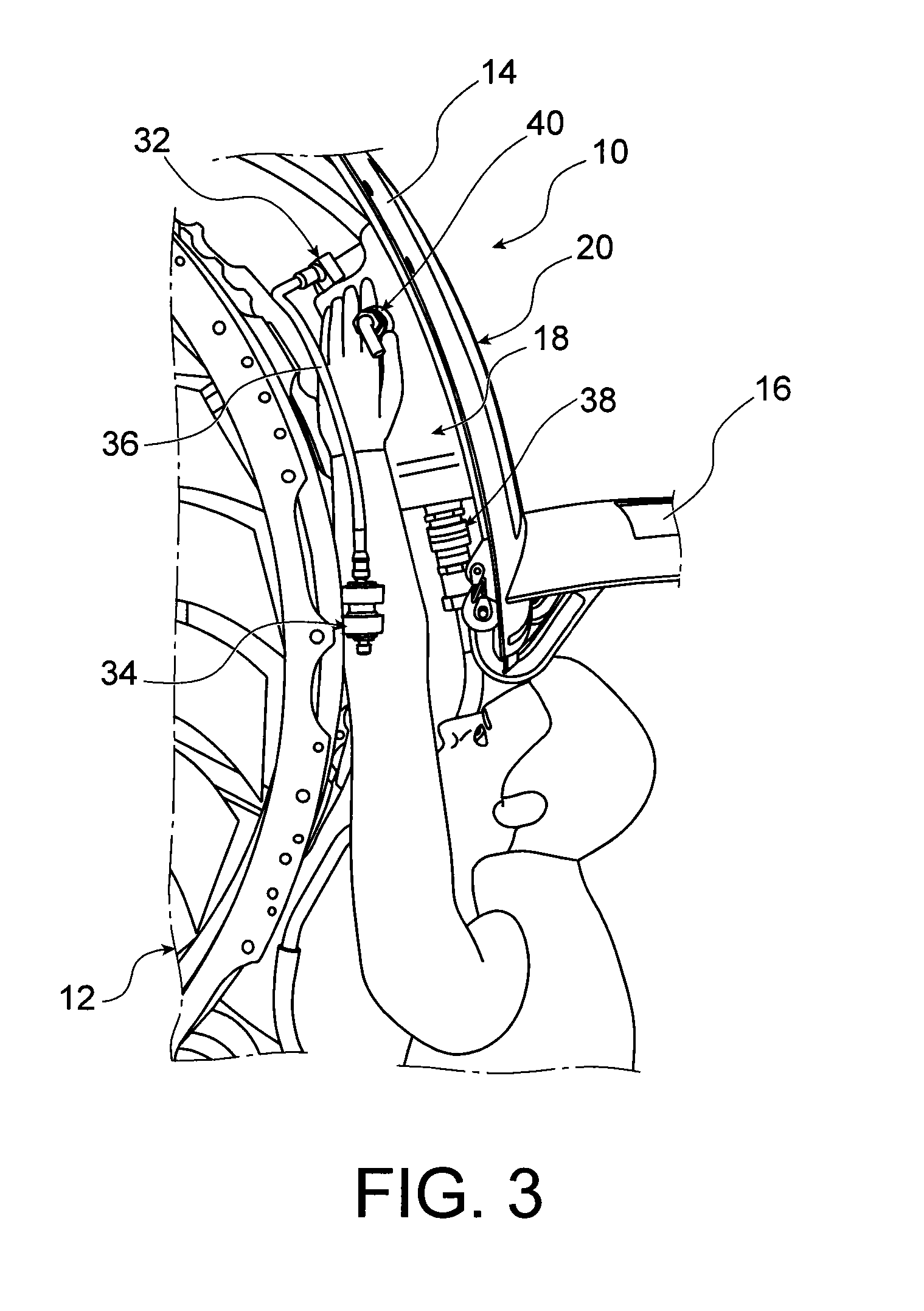
[0041]The tank 18 and the panel 20 form a unit which is added onto the nacelle cowling 10. The means for fastening the panel 20 with the nacelle cowling 10, i.e. the means for fastening this unit onto the nacelle cowling 10 are removable means, making it possible to mount and dismount this sub-unit with the nacelle cowling 10 at any time, identically to the mounting and...


PUM


Abstract

The invention proposes an arrangement of a tank of lubrication liquid for an aircraft turbomachine (12), under a nacelle cowling (10) covering said turbomachine (12), with the tank being arranged in the volume located between the turbomachine (12) and the nacelle cowling (10), with the nacelle cowling (10) comprising an opening (22) for access to said volume,characterised in that the tank (18) is fastened to an internal face (20a) of a panel (20) closing off said opening (22), with the unit formed by the panel (20) and the tank being added onto the nacelle cowling (10) and able to be mounted and dismounted from the nacelle cowling (10).

Description

TECHNICAL FIELD[0001]The invention relates to an arrangement for the mounting of an oil tank of a turbomachine between the external cowling of the nacelle and the intermediate casing, which defines the external portion of the turbomachine.[0002]The invention relates more particularly to the mounting of an oil tank at a distance from the pump of the lubrication system, as such making it possible to optimise the space dedicated to this tank, and limiting the problems relating to the interface and to the mechanical connection of the tank with the turbomachine.PRIOR ART[0003]A conventional turbomachine comprises, among other components, a gear box, commonly referred to as “accessory gear box” (AGB), which drives other components of the turbomachine by taking energy from the turbomachine.[0004]The lubrication circuit of the turbomachine comprises a hydraulic pump driven by the gear box and a tank of lubrication liquid which is commonly mounted in the vicinity of the gear box, in a zone r...

Claims


Application Information

Patent Timeline
IPC IPC(8): B64D29/00F02C7/06B64D47/00
CPCB64D29/00F02C7/06B64D47/00B64D29/08B64D33/00F02C7/32F16N19/00
Inventor KOHN, THIERRYFERT, JEREMY EDMOND
Owner SN DETUDE & DE CONSTR DE MOTEURS DAVIATION S N E C M A
Learn More