Spring load adjustment structure of contact device and spring load adjustment method of contact device

a contact device and spring load technology, applied in the direction of contact, electromagnetic relay details, electrical equipment, etc., can solve the problems of difficult downsizing of the contact device and the increase in the size of the contact devi

Active Publication Date: 2015-03-19
PANASONIC INTELLECTUAL PROPERTY MANAGEMENT CO LTD
View PDF8 Cites 20 Cited by
  • Summary
  • Abstract
  • Description
  • Claims
  • Application Information

AI Technical Summary

Benefits of technology

[0020]The present invention has been made in view of the above-described problems, and an object of the present invention is to provide a spring load adjustment structure, in which an adjustment plate and a holding portion are easily welded, of a contact device and a spring load adjustment method of a contact device.
[0035]As described above, the present invention has an effect that the adjustment plate and the holding portion (first and second holding portions) can be welded easily.

Problems solved by technology

However, when the size of the electromagnet block is increased, the size of the contact device increases, thus making downsizing of the contact device difficult.

Method used


Image

  • Spring load adjustment structure of contact device and spring load adjustment method of contact device
  • Spring load adjustment structure of contact device and spring load adjustment method of contact device
  • Spring load adjustment structure of contact device and spring load adjustment method of contact device

Examples


embodiment

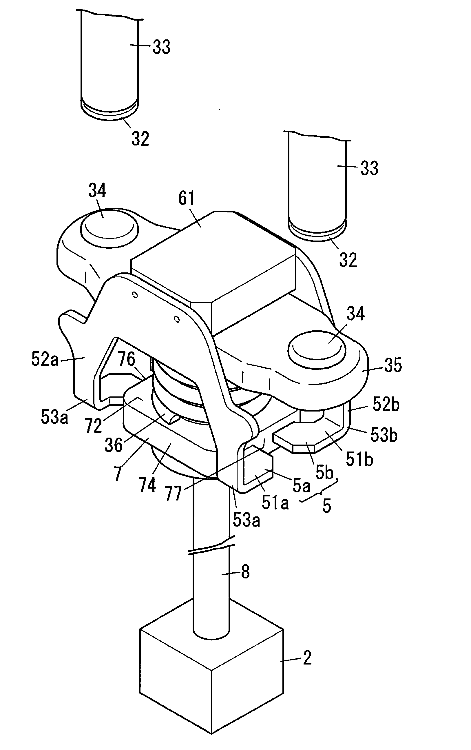
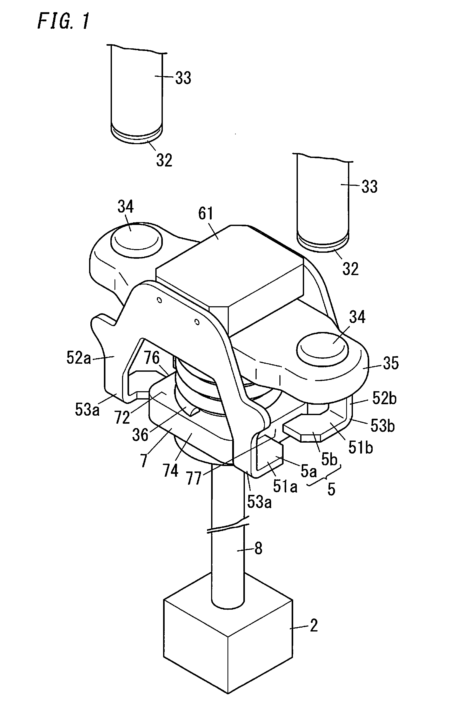
[0050]A contact device of the present embodiment will be described with reference to FIGS. 1 to 4. Note that description will be given using upper, lower, right, and left in FIG. 1 as references, and the direction orthogonal to the upper and lower, and right and left directions is the front and rear direction. The up and down direction is an axial direction (first direction) of a movable shaft 8, the right and left direction is a direction in which movable contacts 34 are arranged side by side (second direction), and the front and rear direction is a third direction orthogonal to the first direction and the second direction. Also, in the up and down direction, upward and upward direction are defined as a first side in the first direction, and downward and downward direction are defined as a second side in the first direction.

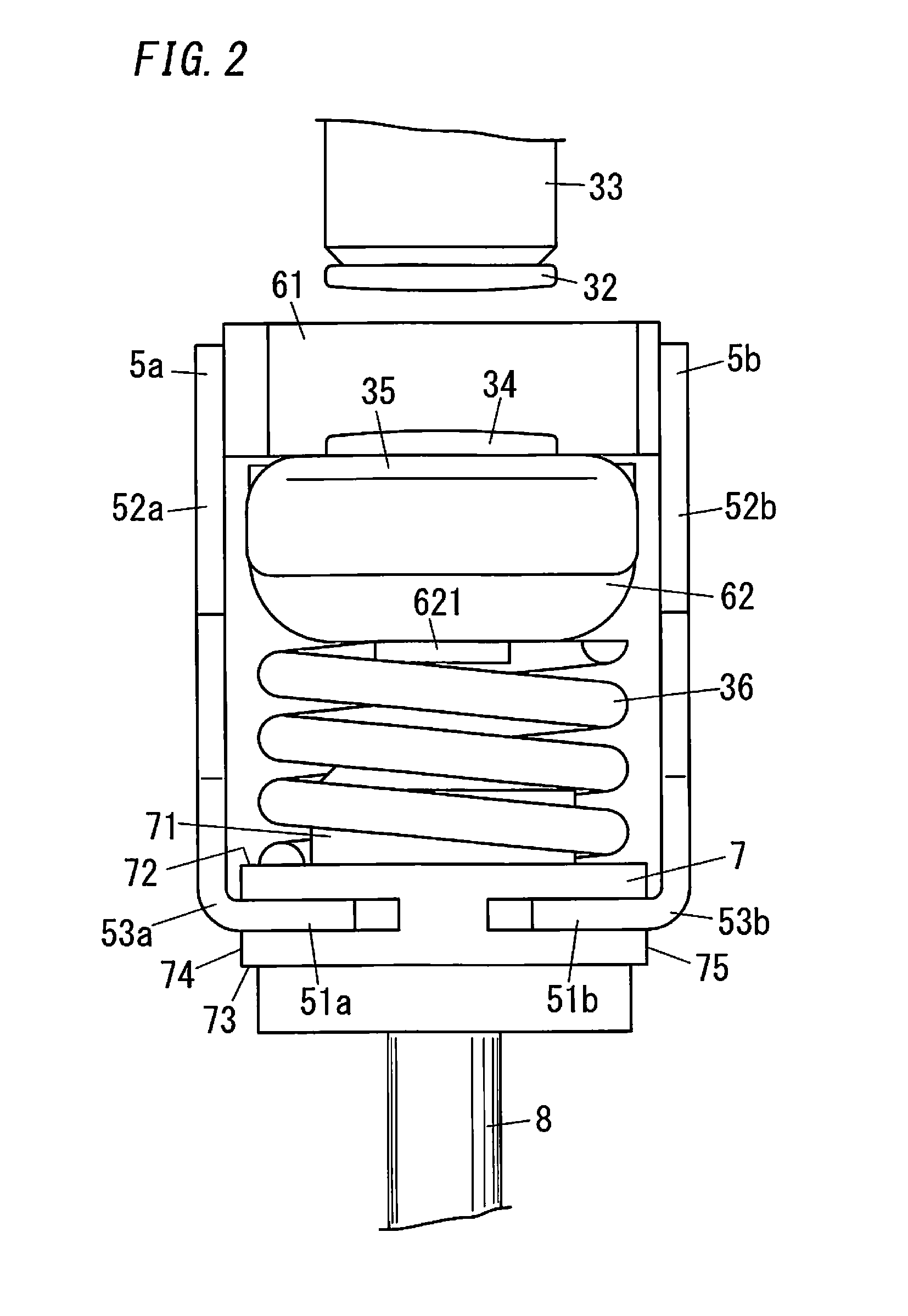
[0051]The contact device of the present embodiment includes, as shown in FIGS. 1 and 2, a pair of fixed terminals 33 respectively including fixed contacts 32, a...


PUM


Abstract

A contact device includes: fixed terminals; a movable contact maker; a pressing spring; an adjustment plate that comes into contact with an upper face of the movable contact maker; a holding; a movable shaft; and an electromagnet block. The holding portion is divided into first and second holding portions that are separated from each other. The first and second holding portions are electrically connected to each other via only the adjustment plate, due to the adjustment plate being sandwiched by a first side plate of the first holding portion and a second side plate of the second holding portion. The adjustment plate is moved in extending and contracting directions of the pressing spring, and the adjustment plate and each of the first and second side plates are subjected to resistance welding at a position at which pressing force of the pressing spring is a predetermined value.

Description

TECHNICAL FIELD[0001]The present invention relates to a spring load adjustment structure of a contact device and a spring load adjustment method of a contact device.BACKGROUND ART[0002]Heretofore, contact device has been provided in which a movable shaft is moved in the axial direction due to turning on / off energization of an electromagnet block, and movable contacts are brought into contact with and separated from fixed contacts, in conjunction with movement of the movable shaft. The contact device includes a pressing spring that gives biasing force to the movable contacts toward the fixed contacts in order to secure pressing force between the contacts when the movable contacts are in contact with the fixed contacts (closed state).[0003]In recent years, since downsizing of the contact device is desired, downsizing of individual parts of the contact device has been in progress, and the pressing spring has been downsized as well. Here, a coil spring is generally used as the pressing ...

Claims


Application Information

Patent Timeline
Patent Type & Authority Applications(United States)
IPC IPC(8): H01H1/50
CPCH01H1/50H01H49/00H01H1/20H01H1/54H01H50/546H01H2050/025
Inventor ENOMOTO, HIDEKIASAKURA, HIROKAZUYAMADA, TETSUYAYAMAMOTO, RITSUSEKI, NAOKISHIMA, TOSHIYUKIINADOMI, NAOKIIKEDA, YOJI
Owner PANASONIC INTELLECTUAL PROPERTY MANAGEMENT CO LTD
Why Eureka
Try Eureka