
High-q parallel-trace planar spiral coil for biomedical implants

Inactive Publication Date: 2015-03-19
GOLDMAN KEN +2
View PDF6 Cites 12 Cited by
  • Summary
  • Abstract
  • Description
  • Claims
  • Application Information

AI Technical Summary

Benefits of technology

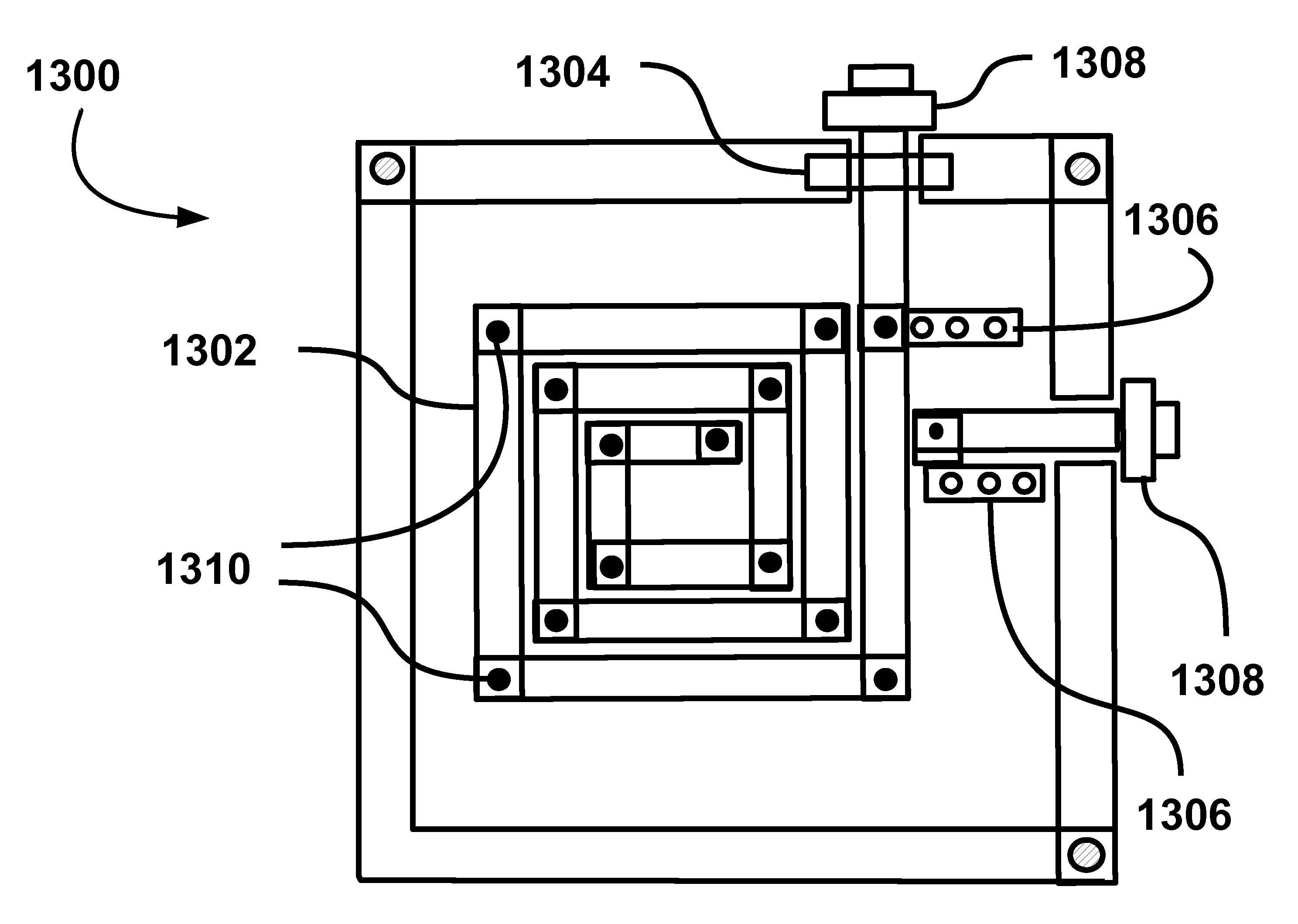
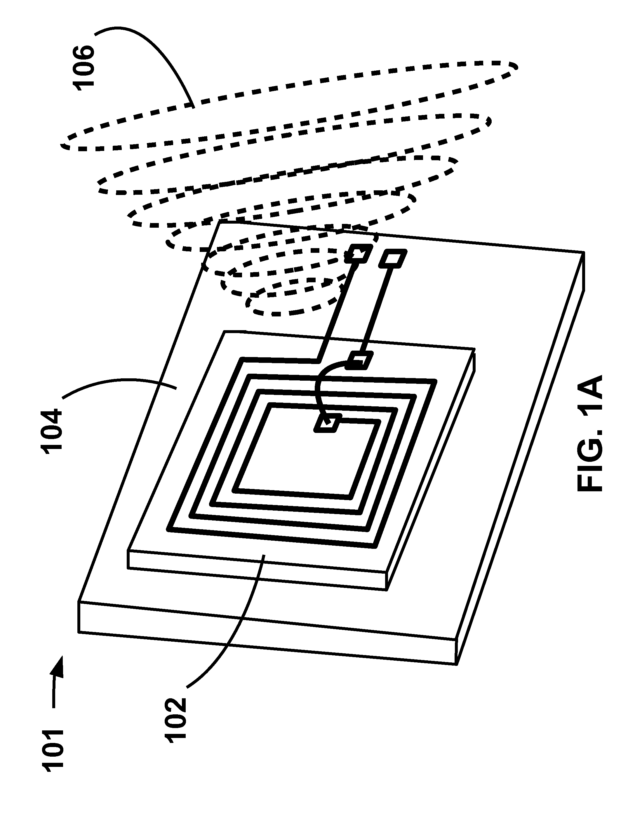
The present invention aims to enhance the quality factor (Q) of an implant's PSC (Printed Spiral Coil) by reducing its resistance. This is achieved by creating a parallel-trace design which reduces the parasitic resistance of the inductor in the LC resonator. The result is a higher Q LC resonator, achieved with the same total cross-section area as a single-trace PSC.

Problems solved by technology

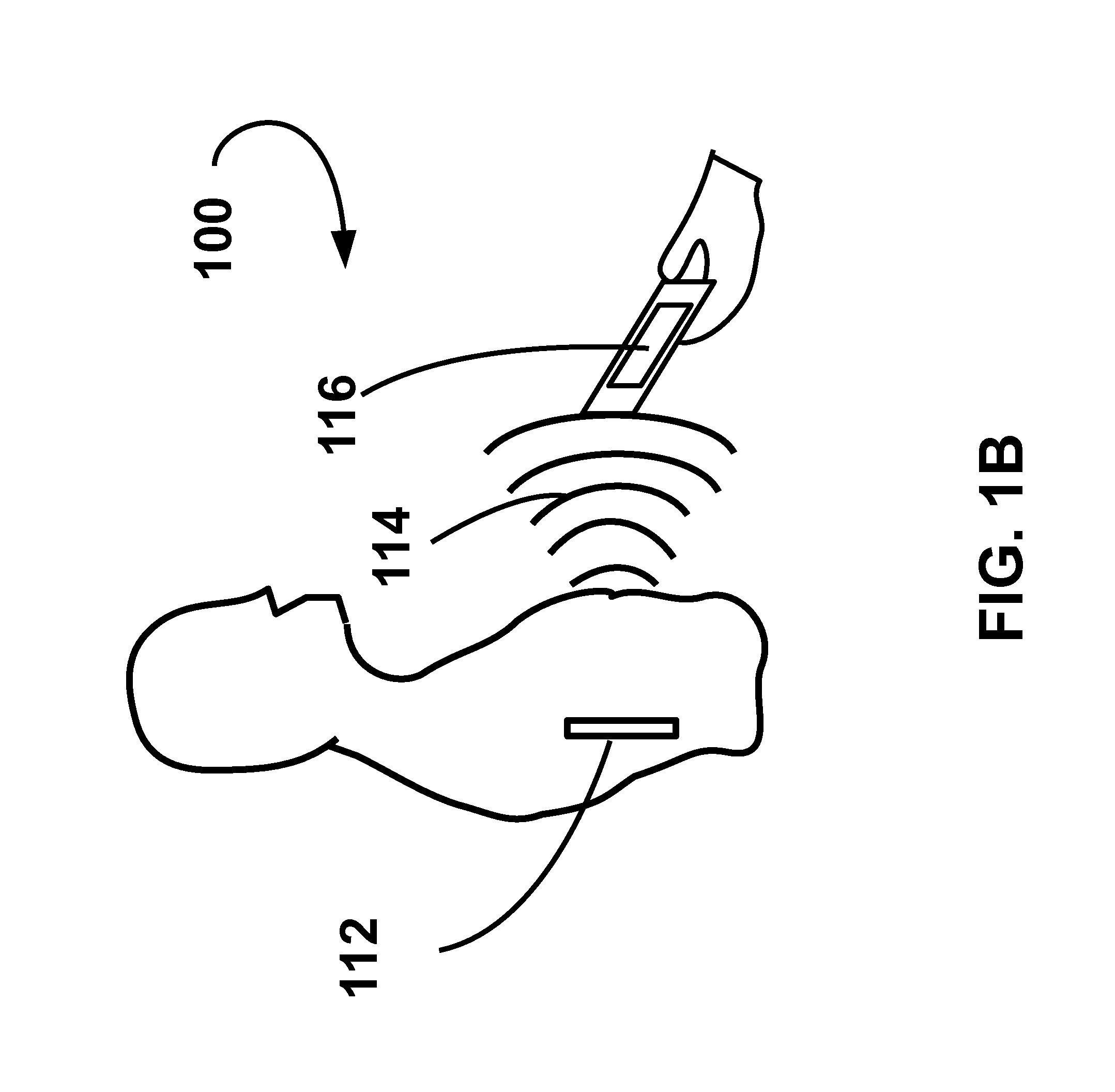
The use of implantable devices to remedy medical conditions is becoming increasingly frequent as the size and cost of such devices shrink.
However, in the implants, a long metal trace forms a large-size PSC with a large cross-section area and a low quality factor (Q).

Method used


Image

  • High-q parallel-trace planar spiral coil for biomedical implants
  • High-q parallel-trace planar spiral coil for biomedical implants
  • High-q parallel-trace planar spiral coil for biomedical implants

Examples


Embodiment Construction

[0026]In the following description, for purposes of explanation, numerous specific details are set forth in order to provide a thorough understanding of the present technology. It will be apparent, however, to one skilled in the art that the present technology can be practiced without these specific details. In other instances, structures and devices are shown in block diagram form only to avoid obscuring the invention.

[0027]Reference in this specification to “one embodiment” or “an embodiment” means that a particular feature, structure, or characteristic described in connection with the embodiment is included in at least one embodiment of the present technology. The appearance of the phrase “in one embodiment” in various places in the specification are not necessarily all referring to the same embodiment, nor are separate or alternative embodiments mutually exclusive of other embodiments. Moreover, various features are described which may be exhibited by some embodiments and not by...


PUM


Abstract

A parallel-trace spiral coil comprising a plurality of electrically-isolated, parallel connected metal traces with high Q factor for use in bio-medical implants.

Description

[0001]This application claims the benefit of U.S. Provisional Application No. 61 / 701,334, filed Sep. 14, 2012.[0002]This invention was made by an agency of the United States Government or under a contract with an agency of the United States Government. The name of the U.S. Government agency: National Institutes of Health, National Institute of Neurological Disorders and Stroke, Phase II and the Government contract number:5R44NS052939-03. A collaborated research project in the Pediatric Device Consortium / UCSF (University of California San Francisco) / SFSU (San Francisco State University)FIELD OF THE INVENTION[0003]Embodiments of the present invention relate to Planar Spiral Coil (PSC) which is an essential component in bio-medical implants (from hereon may be referred to as implants). In particular, the invention relates to the quality factor (Q) of PSCs, which is critical to the performance of an implant.BACKGROUND OF THE INVENTION[0004]The use of implantable devices to remedy medica...

Claims


Application Information

Patent Timeline
IPC IPC(8): H01F27/28H02J7/02H01F38/14H04B5/00
CPCH01F27/2804H01F38/14H02J7/025H04B5/0037H01Q7/00H01Q1/273H01F2027/2809H02J50/23H02J50/12H02J7/00034H02J50/005H04B5/73H04B5/77H04B5/72H04B5/79
Inventor GOLDMAN, KENJIANG, HAOROY, SHUVO
Owner GOLDMAN KEN
Learn More