Controlling Q-factor of filters

a filter and q-factor technology, applied in the field of wireless communication, can solve the problems of many communication systems being affected, noise and/or interference, and undergoing further processing

Active Publication Date: 2006-06-29
WSOU INVESTMENTS LLC +1
View PDF13 Cites 45 Cited by
  • Summary
  • Abstract
  • Description
  • Claims
  • Application Information

AI Technical Summary

Benefits of technology

[0012] In another embodiment, a filter comprises a resonant circuit having an input terminal and an output terminal and a feedback path coupled to the resonant circuit. Stabilization of feedback in the feedback path may provide a variable feedback. By burying the resonant circuit and through the use of one...

Problems solved by technology

Such signal conditioning produces signals that often undergo further processing including filtering, sampling, amplification and/or digitizing because real world signals contain static or dynamic information both wanted and unwanted.
As one example, to maintain a secure link for communications, a frequency hopping technique may be used where the frequency of a transmitter and a receiver changes rapidly, causing noise and/or interference.
Because of this frequency change, many communications systems get affected, often making filtering necessary.
Typically, characteristics of such filters, such as a Q-factor, are fixed and cannot be readily altered.
Although some gains may be obtained through a particular arrangement of the switches, this parallel implementation of individual signal paths for each frequency band adds signifi...

Method used


Image

  • Controlling Q-factor of filters
  • Controlling Q-factor of filters
  • Controlling Q-factor of filters

Examples


Embodiment Construction

[0021] Illustrative embodiments of the invention are described below. In the interest of clarity, not all features of an actual implementation are described in this specification. It will of course be appreciated that in the development of any such actual embodiment, numerous implementation-specific decisions may be made to achieve the developers' specific goals, such as compliance with system-related and business-related constraints, which may vary from one implementation to another. Moreover, it will be appreciated that such a development effort might be complex and time-consuming, but may nevertheless be a routine undertaking for those of ordinary skill in the art having the benefit of this disclosure.

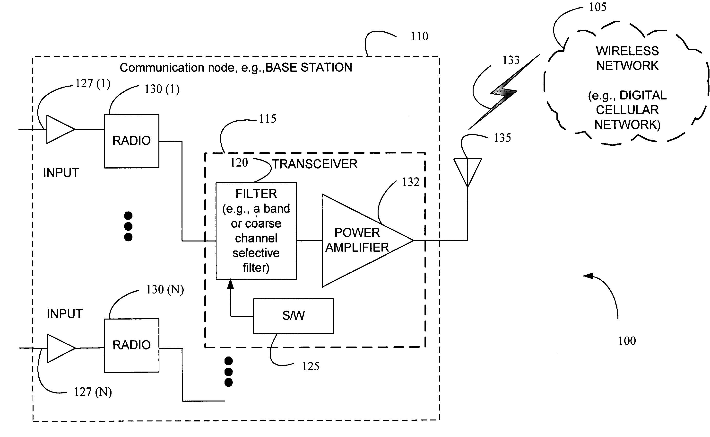
[0022] Generally, a method and apparatus may be used to control a Q-factor for a filter across a multiplicity of frequency band signals. A feedback stabilization technique may stabilize an active feedback to provide a variable feedback in a filter for realizing a desired Q-factor a...


PUM


Abstract

The present invention provides a method and an apparatus for controlling a Q-factor for a filter. The method comprises stabilizing an active feedback to provide a variable feedback in a filter, varying the active feedback based on an input signal to the filter, and producing a desired Q-factor for the filter at a first frequency band, in response to the variable feedback. The method further comprises reconfiguring a center frequency and a bandwidth of the filter based on a channel bandwidth of the input signal to the filter to adjust the Q-factor for the filter in response to a second frequency band different than the first frequency band. By reconfiguring a center frequency and a bandwidth of a filter, the Q-factor for the filter, such as a flexible or reconfigurable filter, may be controlled across a multiplicity of frequency band signals. Using software, for example, a common signal path may be provided for the multiplicity of frequency band signals within a frequency agile radio of a base station by tuning the radio based on a variable feedback through realization of a negative parallel resistance. Thus, tuneability of the Q-factor may provide frequency agile radios that include flexible or reconfigurable filters in a base station to serve different frequency bands without changing hardware. In this way, significant savings associated with frequency agility may be obtained.

Description

BACKGROUND OF THE INVENTION [0001] 1. Field of the Invention [0002] This invention relates generally to telecommunications, and more particularly, to wireless communications. [0003] 2. Description of the Related Art [0004] Most electronic circuits involve signal conditioning of analog, digital and / or mixed signals. Such signal conditioning produces signals that often undergo further processing including filtering, sampling, amplification and / or digitizing because real world signals contain static or dynamic information both wanted and unwanted. As one example, to maintain a secure link for communications, a frequency hopping technique may be used where the frequency of a transmitter and a receiver changes rapidly, causing noise and / or interference. Because of this frequency change, many communications systems get affected, often making filtering necessary. [0005] Generally, filtering is a process or a mathematical operation of removing an undesired component of a signal while allowi...

Claims


Application Information

Patent Timeline
IPC IPC(8): H04B1/04H04B1/16
CPCH03H11/12H04B1/04H04B1/0475H04B2001/0408H03F3/24
Inventor FISCHER, GEORGKAMINSKI, GERHARDECKL, WOLFGANG FRANZ
Owner WSOU INVESTMENTS LLC
Why Eureka
Try Eureka