Eureka AIR delivers breakthrough ideas for toughest innovation challenges, trusted by R&D personnel around the world.

Method and System for Precise Current Matching in Deep Sub-Micron Technology

a technology of deep submicron and current matching, applied in the field of electronic circuit design, can solve the problems of small gate leakage current through the thin oxide mosfet device, significant change in the performance of current mirrors, and decrease in sensitivity to temperature or voltage supply variations

Active Publication Date: 2008-07-03
AVAGO TECH INT SALES PTE LTD
View PDF5 Cites 25 Cited by
  • Summary
  • Abstract
  • Description
  • Claims
  • Application Information

AI Technical Summary

Benefits of technology

[0014]FIG. 5 is a diagram of an output bias control circuit, in accordance with an embodiment of the invention.

Problems solved by technology

The use of current mirrors may frequently lead to decreased sensitivity to variations of parameters such as temperature or voltage supply.
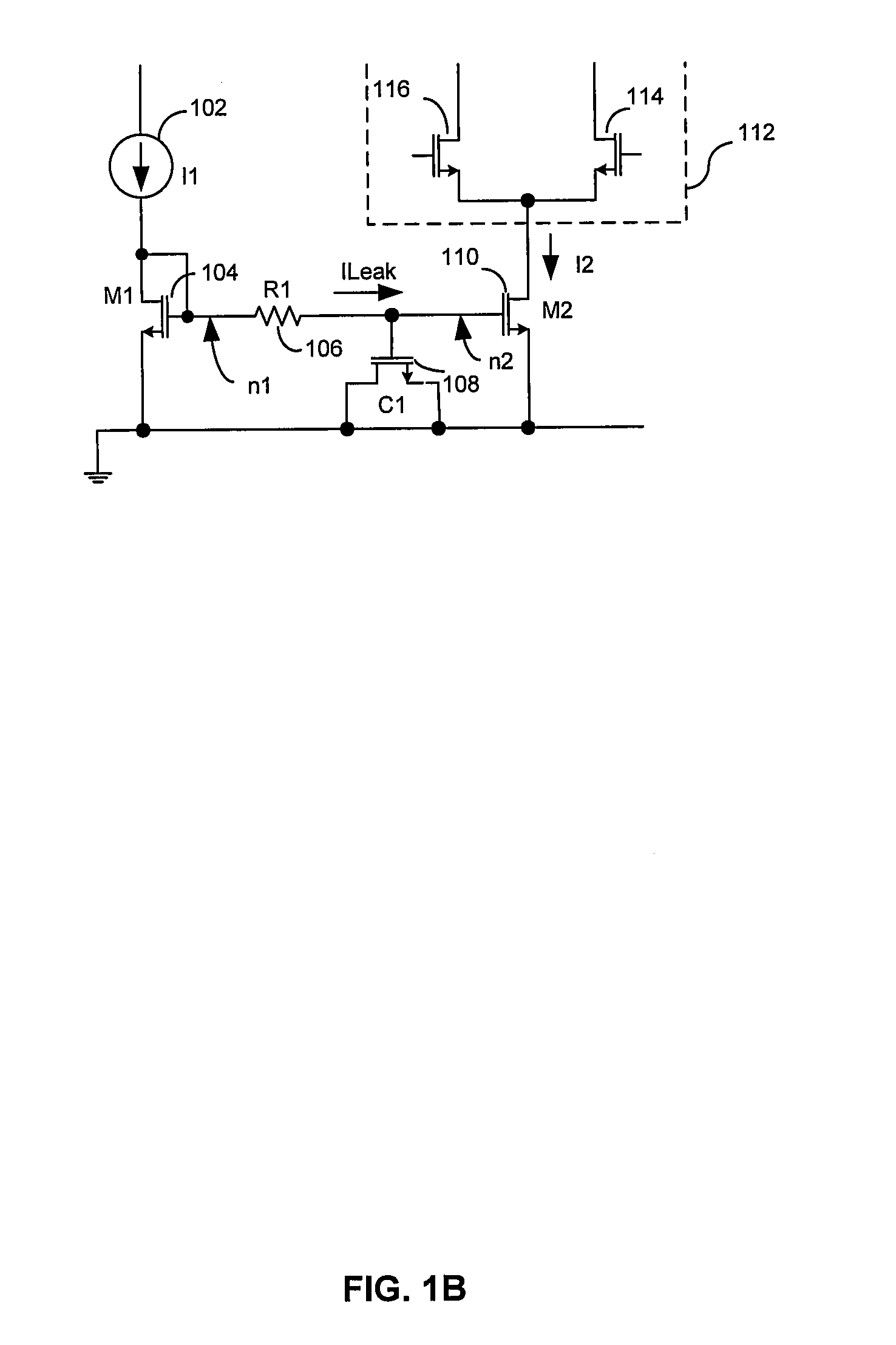
However, modern deep-submicron (fine geometry) Complementary MOS (CMOS) manufacturing processes result in small gate leakage currents through the thin oxide MOSFET devices.
These deviations from theory can lead to significant change in the performance of current mirrors, which may ultimately affect the operation and functionality of integrated circuits comprising these current mirrors.

Method used


Image

  • Method and System for Precise Current Matching in Deep Sub-Micron Technology
  • Method and System for Precise Current Matching in Deep Sub-Micron Technology
  • Method and System for Precise Current Matching in Deep Sub-Micron Technology

Examples


Embodiment Construction

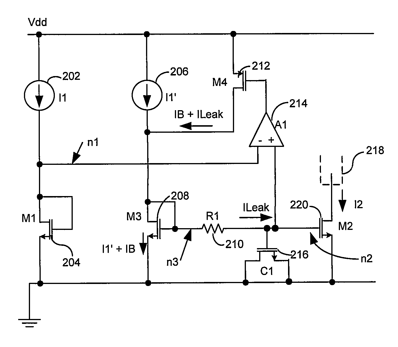
[0015]Certain embodiments of the invention may be found in a method and system for precise current matching in deep sub-micron technology. Aspects of a method and system may comprise adjusting a current mirror to compensate for MOSFET gate leakage currents by using feedback circuits. The feedback circuits may be implemented from active components to create active feedback circuits. If the reference current to be mirrored is noisy, a smoothing effect may be achieved by introducing a low-pass filter coupled to the current mirror. The active feedback may comprise amplifiers, which may comprise one or more amplifier stages. The amplifier may amplify either a bias voltage error or a bias current error. Furthermore, a transimpedance amplifier may be utilized in the feedback loop. The output bias current of the current mirror may be stabilized dynamically during adjusting. In accordance with various embodiments of the invention, multiple current sources may be utilized in the current mirro...


PUM


Abstract

Aspects of a method and system for precise current matching in deep sub-micron technology may include adjusting a current mirror to compensate for MOSFET gate leakage currents by using feedback circuits. The feedback circuits may be implemented from active components to create active feedback circuits. If the reference current to be mirrored is noisy, a smoothing effect may be achieved by introducing a low-pass filter coupled to the current mirror design. The active feedback may comprise amplifiers, which may comprise one or more amplifier stages. The amplifier may amplify either a bias voltage error or a bias current error. Furthermore, a transimpedance amplifier may be utilized in the feedback loop. The output bias current of the current mirror may be stabilized dynamically during adjusting. Multiple current sources may be utilized in the current mirrors.

Description

CROSS-REFERENCE TO RELATED APPLICATIONS / INCORPORATION BY REFERENCE[0001]NoneFIELD OF THE INVENTION[0002]Certain embodiments of the invention relate to electronic circuit design. More specifically, certain embodiments of the invention relate to a method and system for precise current matching in deep sub-micron technology.BACKGROUND OF THE INVENTION[0003]A current mirror is a device comprising an input, an output and a common terminal that is typically connected to a power supply or ground. The input may be connected to a current source. Ideally, the output current will then be equal to the input current and therefore the output is said to mirror the input current, thence the name. This should ideally be true for varying loads at the output.[0004]Current mirrors comprised of active electronic circuit elements have been used extensively in analog electronic integrated circuits both as biasing elements and as load devices for amplifier stages. The use of current mirrors may frequently ...

Claims


Application Information

Patent Timeline
Patent Type & Authority Applications(United States)
IPC IPC(8): H03F3/04G05F3/02
CPCH03F1/301H03F3/04H03F3/345H03F2203/45476H03F2200/462H03F2200/78H03F2203/45244H03F3/45183
Inventor BEHZAD, ARYAAU, STEPHEN CHI-WANGLI, DANDAN
Owner AVAGO TECH INT SALES PTE LTD
Why Eureka
Eureka Blog
Learn More