Gas Turbine Combustion System With In-Line Fuel Reforming And Methods Of Use Thereof

a combustion system and gas turbine technology, applied in the direction of machines/engines, efficient propulsion technologies, lighting and heating apparatus, etc., can solve the problems of hotter combustion chambers, oscillations that could damage combustion hardware, and conflict between hotter combustion chambers

Inactive Publication Date: 2010-12-02
GENERAL ELECTRIC CO
View PDF23 Cites 22 Cited by
  • Summary
  • Abstract
  • Description
  • Claims
  • Application Information

AI Technical Summary

Problems solved by technology

The demand for higher efficiencies which results in hotter combustion chambers conflicts to an extent with the regulatory requirements for low emission DLN gas turbine combustion systems.
One effect of operating in a lean premixed combustion mode is that the combustor can experience unwanted pressure oscillations.
Depending on the magnitude of the oscillation amplitude, these pressure oscillations could damage combustion hardware.
In addition, if the fuel-air mixture in a combust...

Method used


Image

  • Gas Turbine Combustion System With In-Line Fuel Reforming And Methods Of Use Thereof
  • Gas Turbine Combustion System With In-Line Fuel Reforming And Methods Of Use Thereof
  • Gas Turbine Combustion System With In-Line Fuel Reforming And Methods Of Use Thereof

Examples


Embodiment Construction

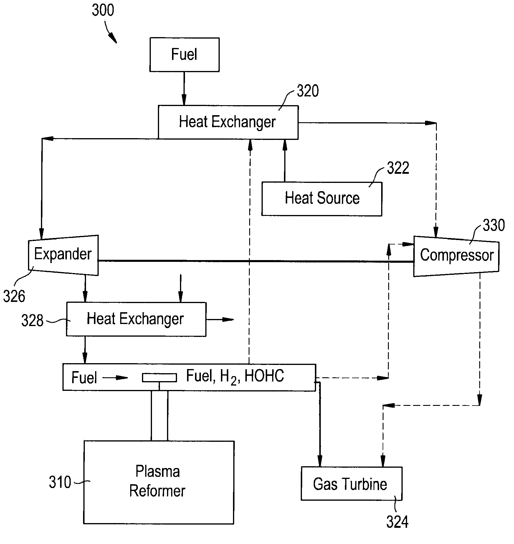
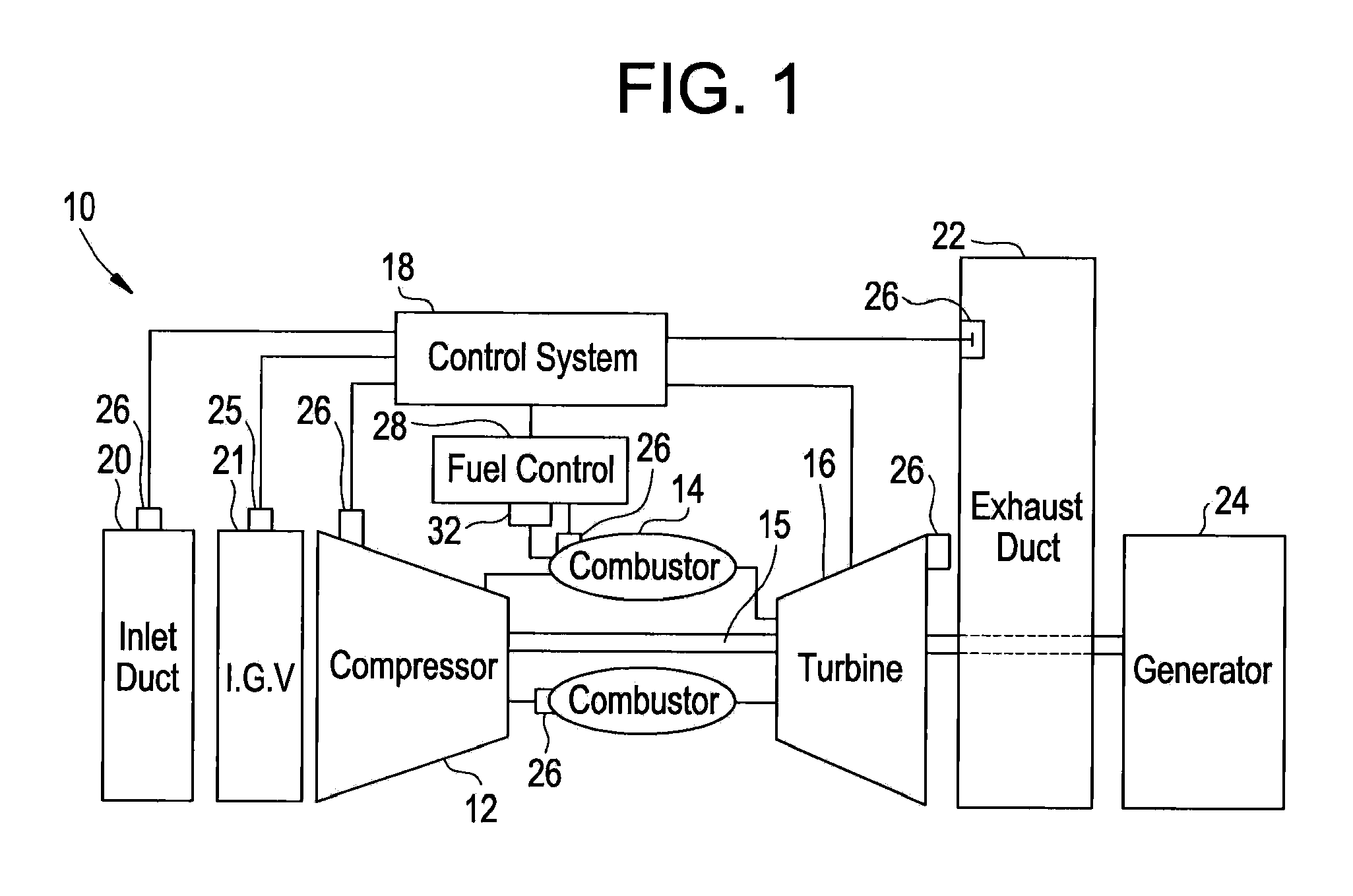
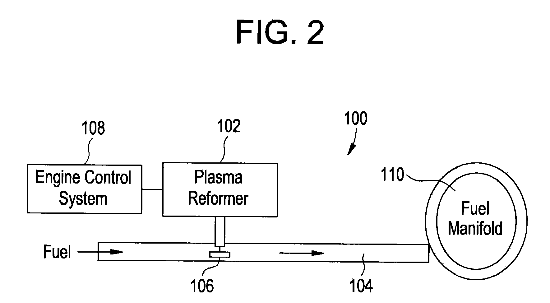
[0019]Described herein are gas turbine engine combustion systems, and more particularly, methods and apparatus for in-line fuel reforming to enhance the operability of the combustion systems. The gas turbine engine combustion systems utilize a plasma reformer system in fluid communication with one or more of the fuel circuits to partially reform a small fraction of the fuel and increase fuel reactivity. As used herein, the term “in-line” is generally intended to mean the plasma reformer system is an integral component of the turbine fuel system. The plasma reformer system may be disposed within the fuel control system, and in some embodiments within the fuel flow path of one or more fuel circuits of the fuel control system. The plasma reformer system, therefore, can improve combustor performance such as dynamics, flame stability and emissions, while limiting power consumption by providing on-demand fuel conditioning to a fraction of the fuel within the gas turbine engine combustion ...


PUM


Abstract

A process for providing a fuel supplied to one or more combustors in a gas turbine engine system, comprising: reforming a fraction of the fuel in one or more fuel circuits of the gas turbine combustion system with a plasma reformer system to form at least one of hydrogen and higher order hydrocarbons to be supplied to the one or more combustors with a remaining fraction of the fuel; and controlling at least one of power and fuel flow to the plasma reformer system with an active feedback control system.

Description

BACKGROUND OF THE INVENTION[0001]This disclosure relates generally to gas turbine engine combustion systems, and more particularly, to methods and apparatus for fuel reforming to enhance the operability of the combustion systems.[0002]Gas turbine engines typically include a compressor section, a combustor section, and at least one turbine section. The compressor discharge air is channeled into the combustor where fuel is injected, mixed and burned. The combustion gases are then channeled to the turbine, which extracts energy from the combustion gases.[0003]Gas turbine engine combustion systems operate over a wide range of flow, pressure, temperature and fuel / air ratio operating conditions. Control of combustor performance, including combustor stability, emissions and dynamics, is required to achieve and maintain satisfactory overall gas turbine engine operation and to achieve acceptable emissions levels, particularly nitrogen oxides (NOx), carbon monoxide (CO), and unburned hydrocar...

Claims


Application Information

Patent Timeline
IPC IPC(8): F02C6/18
CPCC01B3/342C01B2203/0861F02C3/28F23C2900/03002F23C2900/99005F23C2900/9901Y02E60/324F23K2301/10F23N1/002F23N2021/10F23N2041/20F23R3/36F23R2900/00002F23K5/08F23N2221/10F23N2241/20F23K2300/10Y02T50/60Y02E60/32
Inventor KRAEMER, GILBERT OTTOGOLDMEER, JEFFREY SCOTTHERBON, JOHN THOMASYILMAZ, ERTAN
Owner GENERAL ELECTRIC CO
Why Eureka
Try Eureka