Sensor time synchronization

Active Publication Date: 2015-03-19
ROBERT BOSCH GMBH
View PDF4 Cites 12 Cited by
  • Summary
  • Abstract
  • Description
  • Claims
  • Application Information

AI Technical Summary

Benefits of technology

[0019]The present invention advantageously makes possible the synchronization of the sensor time with the time of the component which carries out the data fusion, typically the control unit. These days, the sensor normally already implements a sample timer, which is used internally, to determine when the sensor is starting a new measurement. This sample timer is broadened with a sample counter for the sensor time.
[0020]The control unit may advantageously measure very accurately the output data rates of the data samples with regard to their system clock, since sensor time (sample counter, sample timer) makes possible sub-sample accuracy. Thus, the fractional rational ratio of both clocks is ascertained. Thereupon the output rate of the sensor is adjusted, advantageously also sub-sample accuracy

Problems solved by technology

That leads to errors in the calculated target values in the sensor data fusion.
If the data are stored in the digital back end of the respective sensors in a FIFO, the synchronization is even more difficult, since the read instant is the same for all sensor data in the FIFO.
If one calculates back using the dat

Method used


Image

  • Sensor time synchronization
  • Sensor time synchronization
  • Sensor time synchronization

Examples


Embodiment Construction

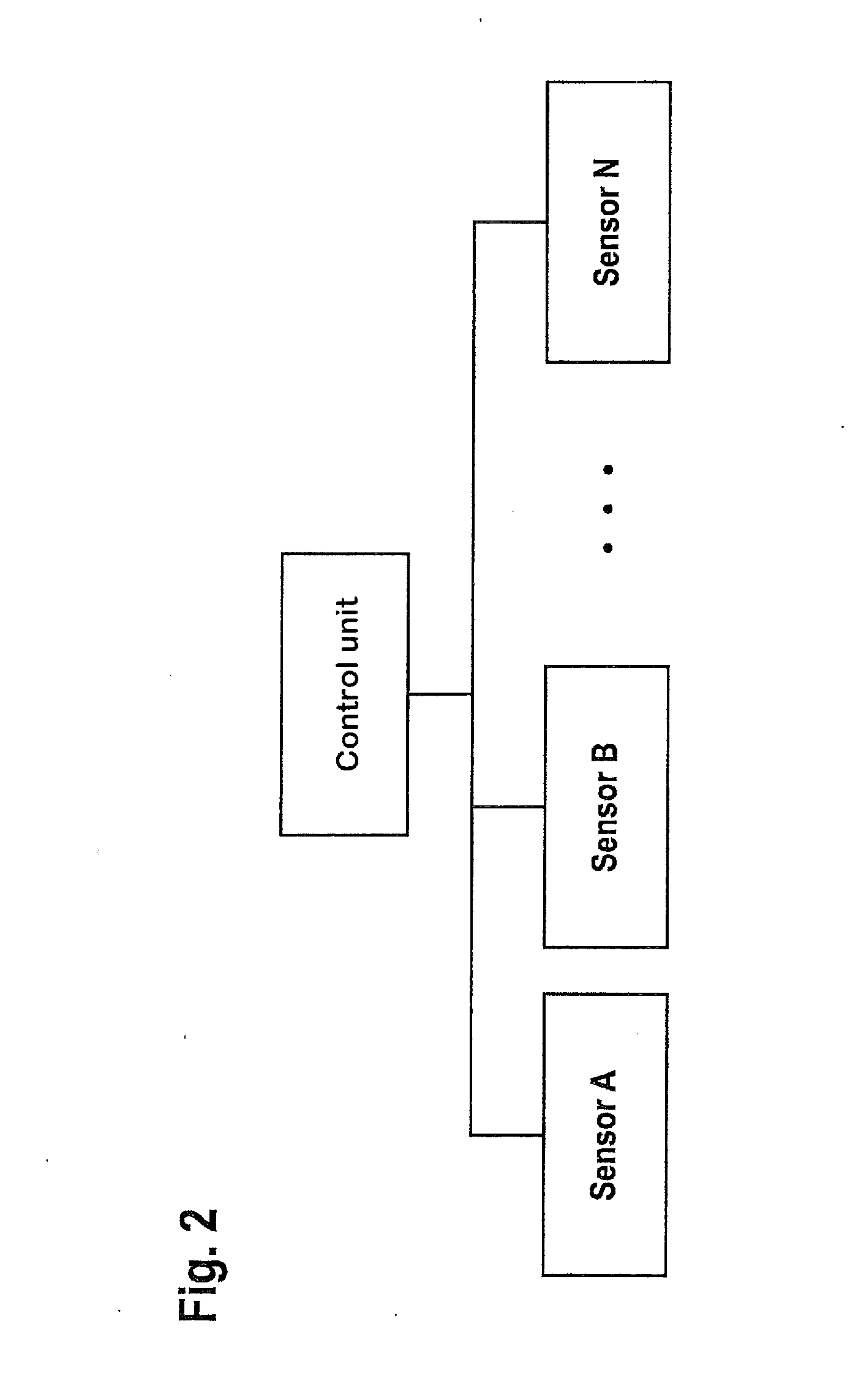
[0030]FIG. 5 shows a sensor having two externally accessible sample timer and sample counter registers. It is known in the related art that one may provide sensors with a sample counter, in order to measure the time between data samples. For this purpose, the sample counter is available internally in the sensor. In the non-published German Patent Application DE 102012207026.5, a sensor is described which includes a sample timer register and a sampler counter register, as is shown in FIG. 5. The sample timer register includes the time period within a sample and is reset at the beginning of each new sample. The sample counter register counts the samples. The content of these two registers forms the sensor time, and is accessible from the outside, for instance, by a control unit. The sensor allows the control unit to read out the sensor time. From this, the control unit is able to assign to each sample of the data output of the sensor an accurate time stamp.

[0031]FIG. 6 shows a sensor ...


PUM


Abstract

A sensor for acquiring measured values and for outputting data samples having at least one first register for storing a sensor time, which includes time information on phase position and/or period of the data samples, the first register being readable out externally. The sensor includes at least one second register, which is writable on externally, and by which the phase position and/or the period of the data samples is able to be set in the sensor. Also described is a sensor system having at least one sensor and an external control unit by which at least the first register is readable and at least the second register is writable. Also described is a sensor-fused system having at least one sensor system having at least two sensors. Also described is a method for setting the phase position and/or the period of data samples in a sensor system or a sensor-fused system.

Description

FIELD OF THE INVENTION[0001]The present invention relates to sensor time synchronization.BACKGROUND INFORMATION[0002]Synchronization of sensor data having display on mobile units is discussed, for instance, in Laid-Open Document US 20110164163 A1. There the discussion relates to the synchronization of sensors and augmented reality in general, and not the method of correcting individual data points and their time discrepancy among one another.[0003]Patent document U.S. Pat. No. 8,050,881 B1 discusses the synchronization of a local clock in the sensor with another clock and interpolation of the times. In this context, only the points in time of (integral) measurements are taken into account, not the delay between the creation of the data and reading them out of the sensor. The asynchronism of different sensors among one another is also not taken into account or actively eliminated.[0004]Patent document U.S. Pat. No. 7,382,780 B1 discusses a subsequent time synchronization with the aid...

Claims


Application Information

Patent Timeline
IPC IPC(8): G01D18/00G01D3/02
CPCG01D3/022G01D18/004
Inventor LAMMEL, GERHARDBICHLER, RUDOLFRETZ, GUIDODORSCH, RAINER
Owner ROBERT BOSCH GMBH
Why Eureka
Try Eureka