Catalyst retainer for radial flow reactor

a technology of catalyst and radial flow reactor, which is applied in the direction of hydrocarbon oil treatment hydrocarbon oil treatment, etc., can solve the problems of increasing operating pressure and reducing the conversion rate of paraffin to olefin, so as to prevent collision and attrition of catalyst particles, reduce fluid tangential velocity, and improve flow

Inactive Publication Date: 2015-03-19
UOP LLC
View PDF3 Cites 33 Cited by
  • Summary
  • Abstract
  • Description
  • Claims
  • Application Information

AI Technical Summary

Benefits of technology

[0013]An advantage of this invention is to reduce the fluid tangential velocities on the catalyst bed free surface and prevent catalyst particle collisions and attrition in the seal area. A reactor catalyst retainer of the invention includes a perforated louver that diffuses the flow within the catalyst seal space permitting the flow to reach the catalyst bed more uniformly. The invention introduces the fluid to the top catalyst free surface in a more uniform manner and hence improves the flow and prevents particle movement and attrition.

Problems solved by technology

This mechanism may increase the operating pressure which in turn may lead to lower paraffin to olefin conversion rate.

Method used


Image

  • Catalyst retainer for radial flow reactor
  • Catalyst retainer for radial flow reactor
  • Catalyst retainer for radial flow reactor

Examples


Embodiment Construction

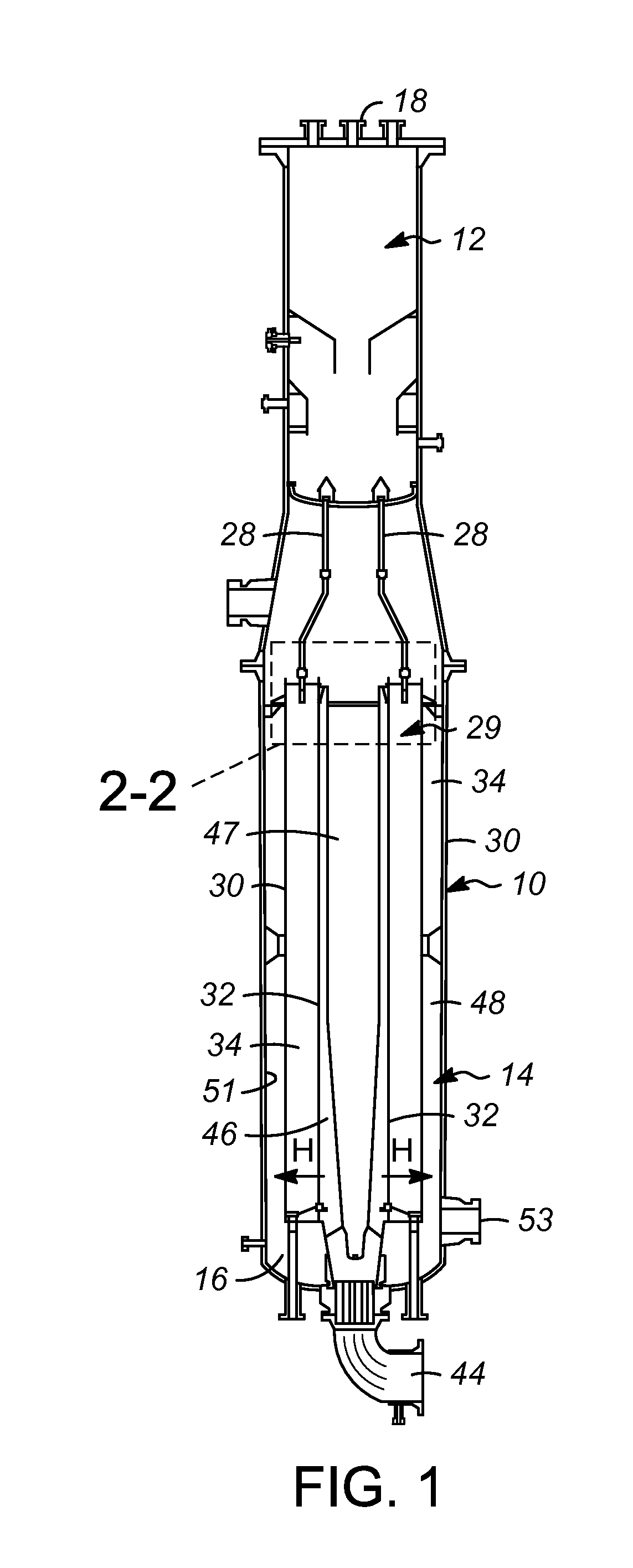
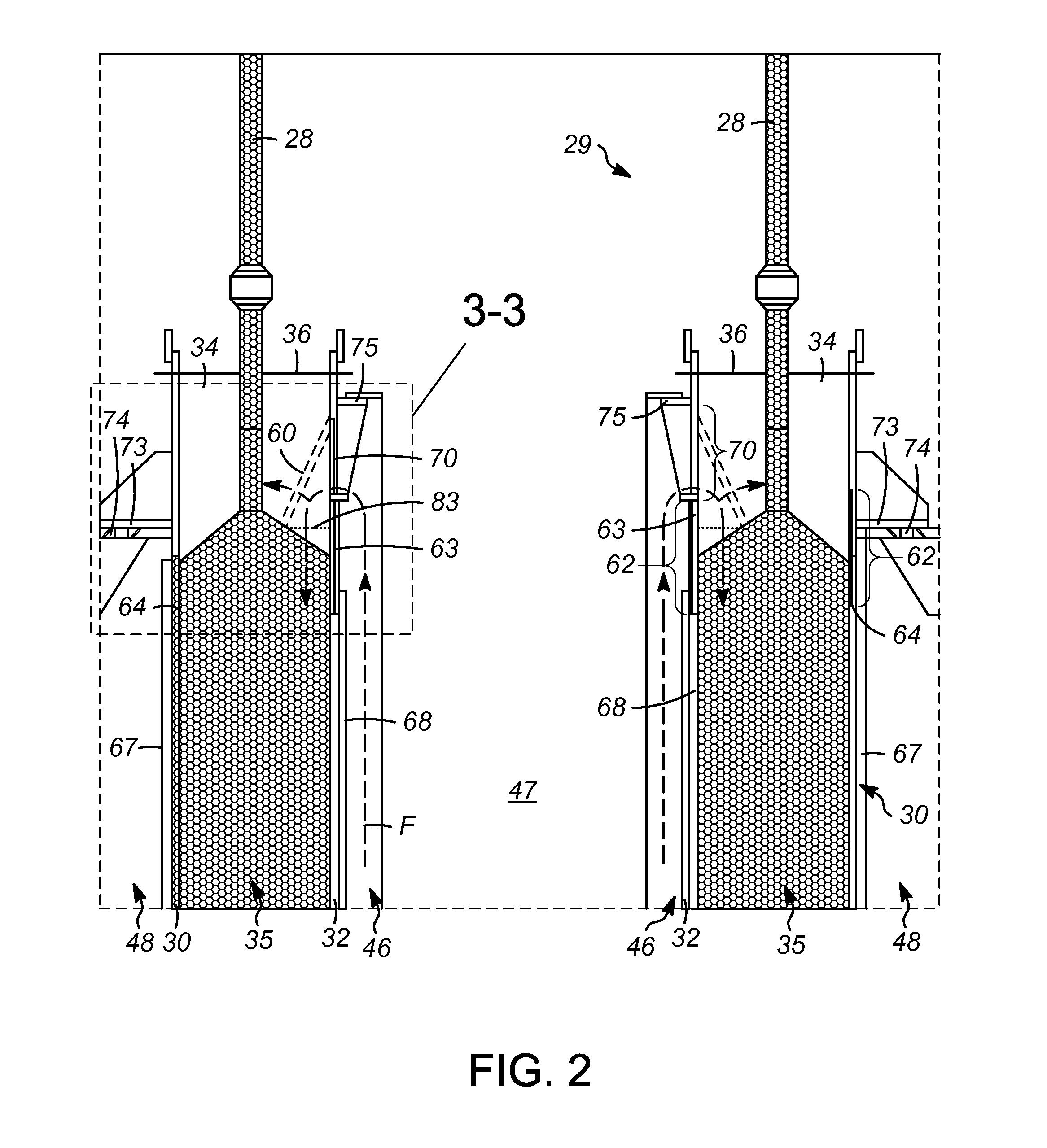
[0019]Looking first at FIGS. 1 and 2, there is shown a cross-section of a reactor for converting paraffinic hydrocarbons to olefinic hydrocarbons by contact with a particulate catalyst. The vertically oriented reactor vessel has a cylindrical shell 10 that confines a catalyst hopper 12, a reactor section 14, and a catalyst collection zone 16. At the top of catalyst hopper 12, there is a catalyst loading nozzle 18 for filling hopper 12 with fresh or regenerated catalyst particles. A series of particle supply conduits 28 are spaced around the bottom of hopper 12 and communicate catalyst particles to the reactor section 14. When used in a reactor, these particle supply conduits 28 are also referred to as catalyst transfer pipes.

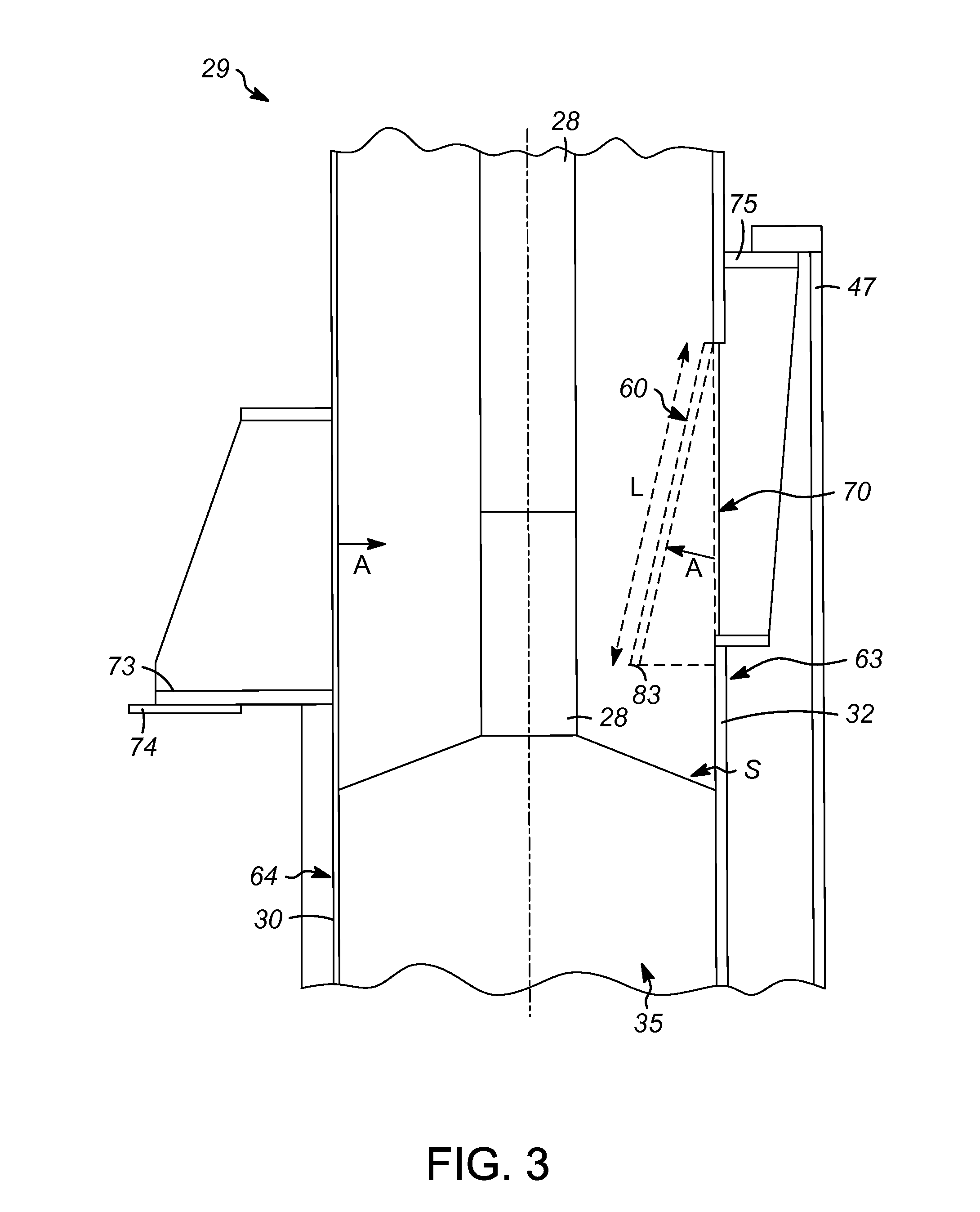
[0020]The reactor section 14 includes a catalyst retainer 29 in the form of an outer retention screen 30 that surrounds a vertically oriented inner retention screen 32. In the embodiment of FIG. 1, the cylindrical shape of the outer retention screen 30 and the i...


PUM


Abstract

A catalyst retainer includes an inner particle retention device having apertures and a first non-apertured section; and an outer particle retention device having apertures and a second non-apertured section. The inner and the outer particle retention devices are spaced apart to define a particle retaining space of the retainer. The first non-apertured section and the second non-apertured section define a blanked-off section of the particle retaining space, and the blanked-off section is spaced from an end of the particle retaining space. The catalyst retainer also includes a louver with at least a portion located between the blanked-off section and the end of the particle retaining space. The louver extends into the particle retaining space at an angle with respect to an inner surface of the inner particle retention device. The louver introduces the fluid to the top catalyst free surface in a more uniform manner and hence prevents particle movement and attrition.

Description

BACKGROUND OF THE INVENTION[0001]1. Field of the Invention[0002]The disclosure relates to a catalyst retainer for a radial flow reactor, and more particularly to a radial flow reactor catalyst retainer having a louver in the catalyst seal area.[0003]2. Description of the Related Art[0004]Hydrocarbon conversion processes are common in the refining and petrochemical industry. For example, the production of an alkylene (e.g., propylene) can be obtained by the dehydrogenation of an alkane (e.g., propane) through catalytic dehydrogenation in a radial flow reactor. The reactants in a radial flow catalytic dehydrogenation process pass through a reaction zone containing catalyst in a substantially horizontal direction in the case of a vertically oriented cylindrical reactor. Often, the catalyst is retained in an annular zone between an inner particle retention device (e.g., an inlet screen) and an outer particle retention device (e.g., an outlet screen) in the forms of inner and outer cylin...

Claims


Application Information

Patent Timeline
Patent Type & Authority Applications(United States)
IPC IPC(8): B01J8/02
CPCB01J8/0242B01J8/12B01J2208/00884B01J2208/00938C10G49/002C10G2400/22
Inventor IDDIR, HADJIRAVETTER, MICHAEL J.ZIMMERMANN, JOSEPH E.
Owner UOP LLC
Why Eureka
Try Eureka