Ultrasonic flow meter

a flow meter and ultrasonic technology, applied in the direction of velocity propogation, instruments, measurement devices, etc., can solve the problems of low flow rate accuracy, lowered flow rate accuracy, and difficult measurement at low flow rate, so as to suppress the generation of gas bubbles due to such variations in pressure, the effect of lowering the detection accuracy and high accuracy

Active Publication Date: 2015-03-26
SMC CORP
View PDF5 Cites 18 Cited by
  • Summary
  • Abstract
  • Description
  • Claims
  • Application Information

AI Technical Summary

Benefits of technology

[0016]According to the present invention, in the ultrasonic flow meter in which the pair of detection units is disposed in the interior of the casing, the detection units are accommodated respectively while sandwiching therebetween the passage that is formed in the interior of the casing, and the two port members are connected to both ends of the casing. In addition, owing to the fact that the liquid, which is supplied from one of the port members, flows through the communication path formed on an outer circumferential side of the detection unit inside the linearly disposed casing, and thereafter flows to the other one of the port members, variations in pressure are inhibited to a minimum, and ge

Problems solved by technology

Consequently, it is difficult for the flow rate of the liquid to be measured accurately by propagation of the acoustic wave signals.
Along therewith, flow rate accuracy is lowered, together with measurements at low flow rates being difficult to make.
Further, with the ultrasonic flow meters according to Patent Document 1, Pate

Method used


Image

  • Ultrasonic flow meter
  • Ultrasonic flow meter
  • Ultrasonic flow meter

Examples


first embodiment

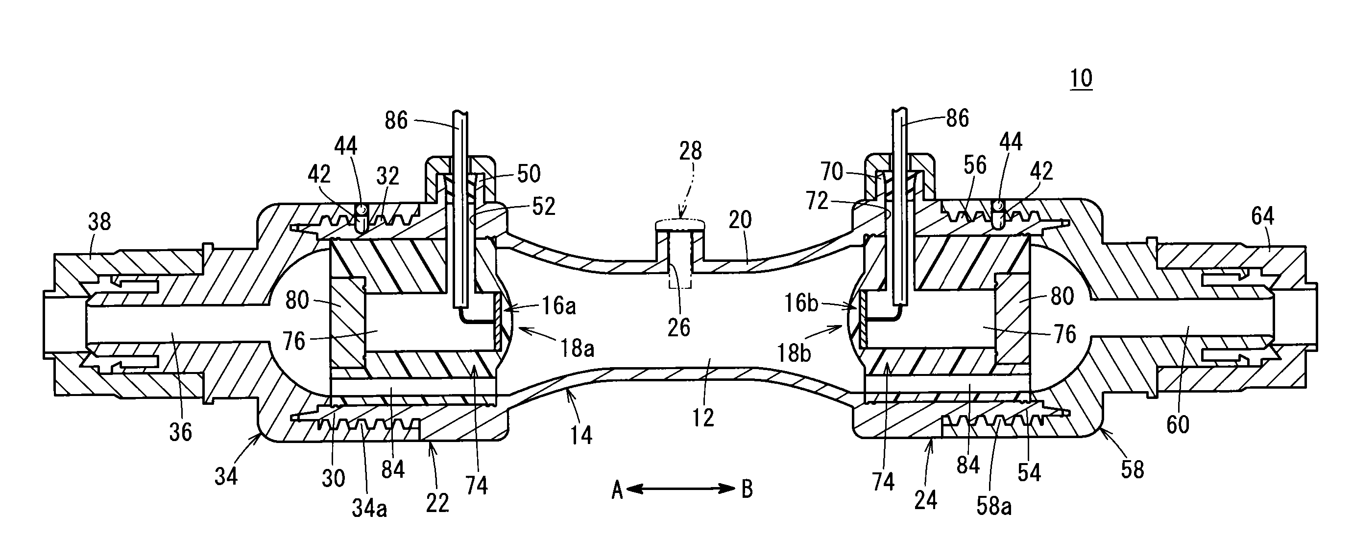
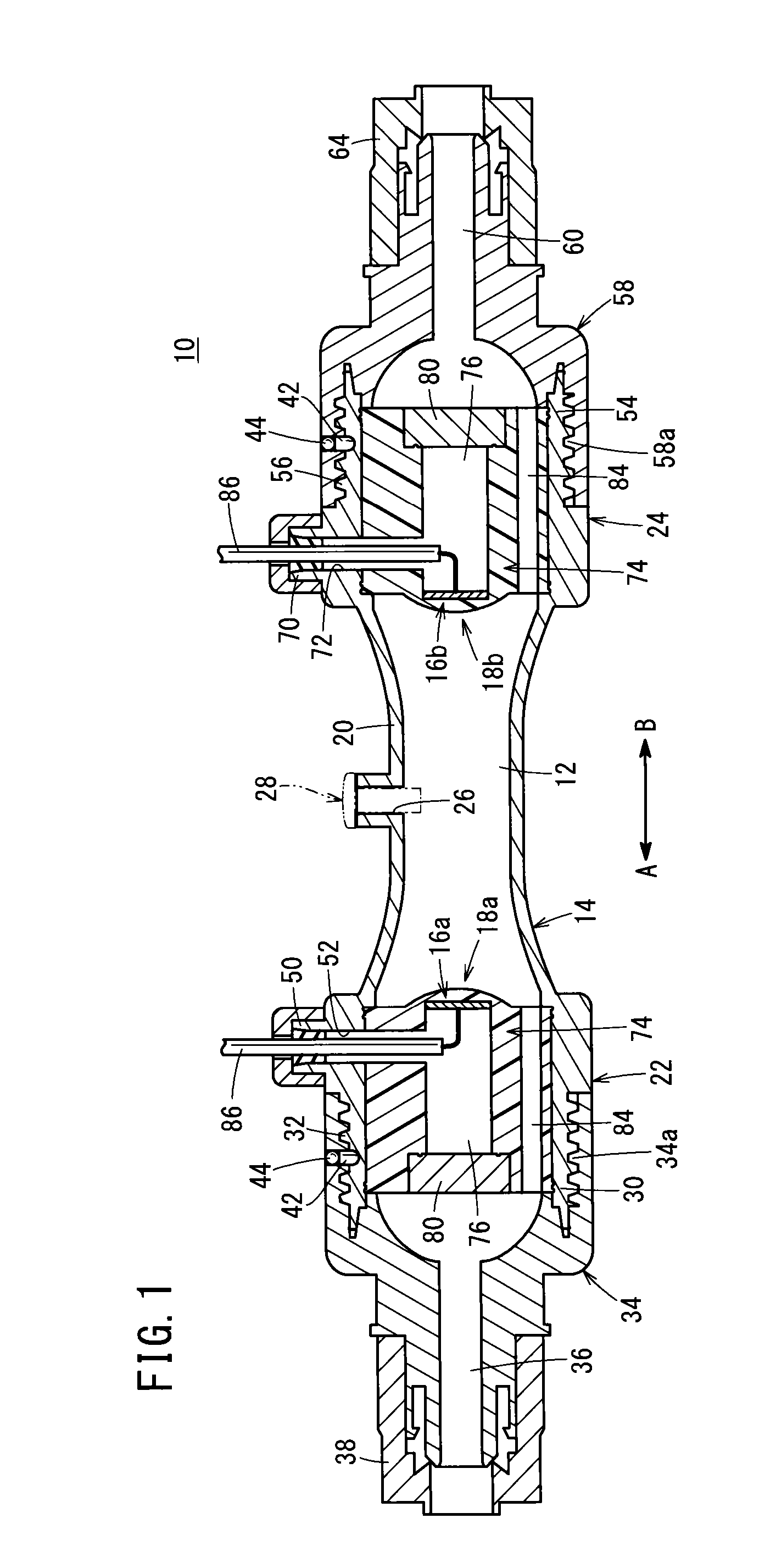
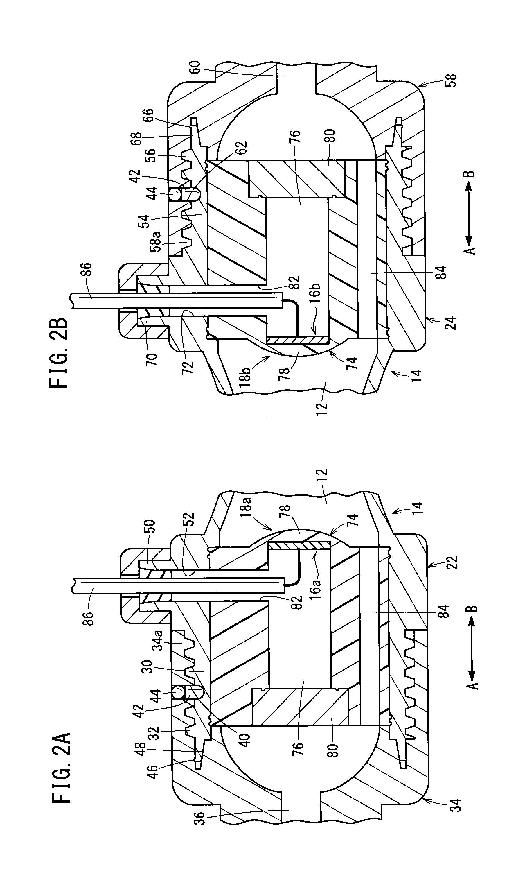
[0053]The ultrasonic flow meter 10 according to the present invention is constructed basically as described above. Next, operations and effects of the ultrasonic flow meter 10 will be described. A liquid is supplied to the supply passage 36 through the tube from a non-illustrated liquid supply source. The liquid flows in the supply passage 36, through the communication holes 84 of one of the detection units 18a, and then flows into the passage 12. Thereafter, the liquid flows through the communication holes 84 of the other of the detection units 18b and flows into the discharge passage 60.

[0054]In the ultrasonic flow meter 10, in a state in which liquid flows inside the passage 12 of the housing 14, acoustic wave signals are transmitted, for example, from the acoustic wave transmitting and receiving unit 16a of the detection unit 18a connected to one end of the housing 14, and the acoustic wave signals propagate inside the liquid while being reflected by the inner wall surface of th...

second embodiment

[0076]In the foregoing manner, with the second embodiment, by providing the conical portions 110, which project with triangular shapes in cross section toward the passage 12 on the other ends of the holders 104 that make up the detection units 102a, 102b, the flow of the liquid through the passage 12 of the housing 14 can be straightened and made to be laminar by the conical portions 110, whereby pressure losses are reduced and generation of gas bubbles can be effectively suppressed. As a result, lowering in detection accuracy caused by the adherence of gas bubbles with respect to the holders 104 of the detection units 102a, 102b can be prevented more effectively.

[0077]Further, by providing the vibration absorbing members 106 in the interiors of the conical portions 110 on the holders 104, the intensity of the acoustic wave signals that are transmitted and received by the acoustic wave transmitting and receiving units 16a, 16b is increased, and measurement of the flow rate can be pe...


PUM


Abstract

An ultrasonic flow meter is equipped with a housing through which a liquid flows, and a pair of detection units disposed on opposite ends of the housing and including acoustic wave transmitting and receiving units capable of transmitting and receiving acoustic wave signals. Paired connecting plugs are connected respectively to both ends of the housing. In addition, a supply passage of one of the connecting plugs, a conduit of the housing, and a discharge passage of another of the connecting plugs are disposed on a straight line. A liquid supplied to the supply passage flows through a passage of the conduit and to the discharge passage. Consequently, a flow rate of the liquid is measured based on the propagation time of the acoustic wave signals, which are transmitted and received by the acoustic wave transmitting and receiving units.

Description

CROSS-REFERENCE TO RELATED APPLICATION[0001]This application is based upon and claims the benefit of priority from Japanese Patent Application No. 2013-197266 filed on Sep. 24, 2013, the contents of which are incorporated herein by reference.BACKGROUND OF THE INVENTION[0002]1. Field of the Invention[0003]The present invention relates to an ultrasonic flow meter for detecting the flow rate of a liquid based on a propagation velocity difference exhibited when acoustic waves are propagated through the liquid.[0004]2. Description of the Related Art[0005]Heretofore, an ultrasonic flow meter has been known in which, for example, paired transducers are arranged respectively on an upstream side and a downstream side of a conduit through which a liquid flows. Ultrasonic waves transmitted from one of the transducers are reflected by an inner wall surface of the conduit and are received by another of the transducers, and a flow velocity or a flow rate of the liquid is measured based on a diffe...

Claims


Application Information

Patent Timeline
IPC IPC(8): G01F1/66
CPCG01F1/66G01F1/662G01H5/00
Inventor MARUYAMA, TETSUROSUZUKI, TAKAMITSU
Owner SMC CORP
Why Eureka
Try Eureka