Brake devices

a technology of anti-locking and brakes, which is applied in the direction of brake cylinders, braking systems, braking components, etc., can solve the problems of difficult to sufficiently reduce brake devices may vibrate and possibly generate noise, and the reciprocating pump may produce a pulsation of pressure, etc., to achieve the effect of reducing the pulsation of hydraulic pressur

Inactive Publication Date: 2007-03-20
ADVICS CO LTD
View PDF11 Cites 0 Cited by
  • Summary
  • Abstract
  • Description
  • Claims
  • Application Information

AI Technical Summary

Benefits of technology

[0007]It is accordingly an object of the present invention to teach improved brake devices that can effectively reduce the pulsation of the hydraulic pressure of a working liquid that may be generated by the operation of a pump incorporated within the hydraulic circuit.
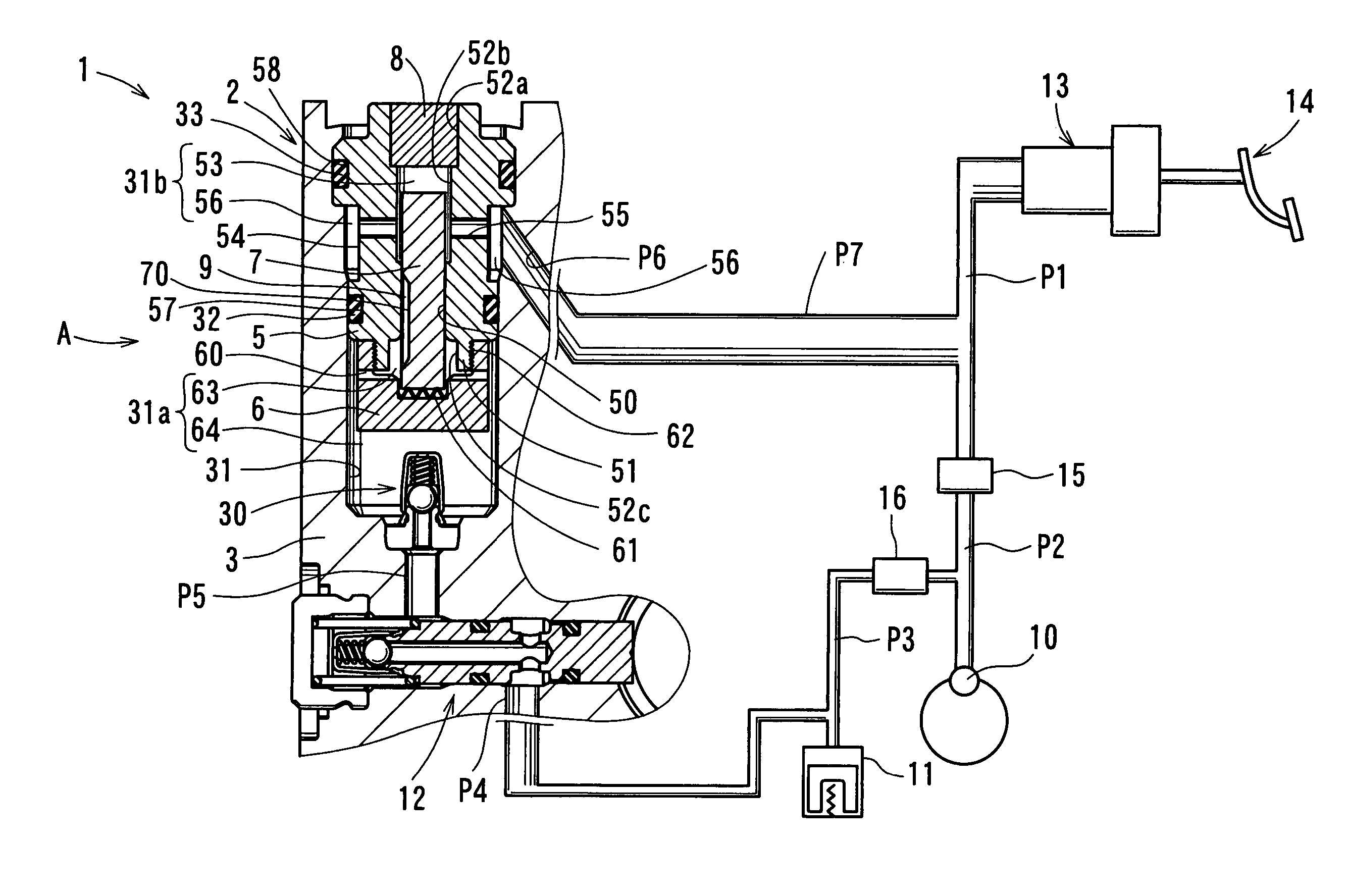
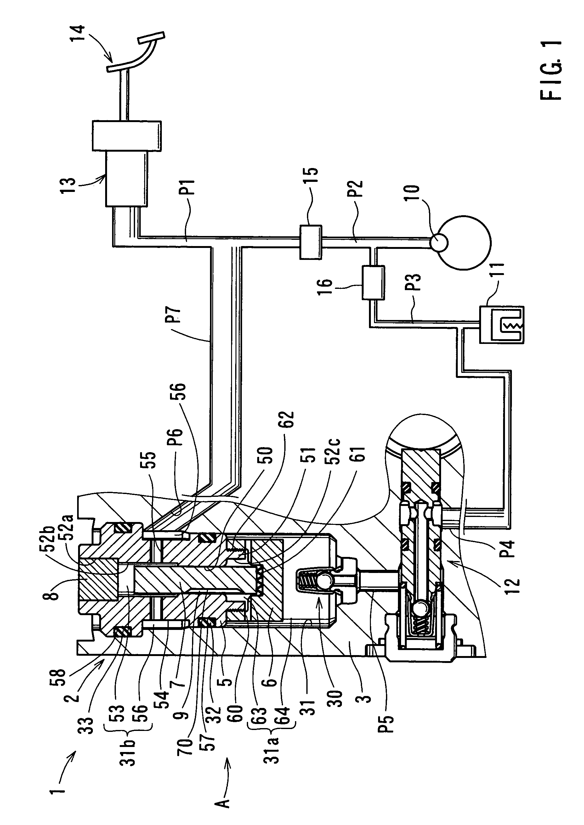
[0008]According to one aspect of the present teachings, brake devices are taught that include a brake cylinder, a reservoir, a pump (such as a reciprocating pump for example), a master cylinder, and a pulsation-reduction device. The reservoir serves to accumulate a working liquid discharged from a brake cylinder. The pump serves to transfer the working liquid accumulated within the reservoir. The master cylinder serves to receive the working liquid discharged from the pump. The pulsation-reduction device serves to reduce the level or the effects of the pulsation of the hydraulic pressure of the working liquid discharged from the pump. The pulsation-reduction device comprises a valve device disposed in a communication channel connecting the downstream side of the pump and the master cylinder. The valve device comprises a spool disposed within the communication channel. The spool is movable along the communication channel in response to the difference in pressure between the pressure in the communication channel on the side of the pump and the pressure in the communication channel on the side of the master cylinder, in order to open and close at least a part of the communication channel allowing the working liquid to move between the two sides of the communication channel.
[0009]Therefore, if the pressure on the side of the pump is greater than the pressure on the side of the master cylinder, the spool may open the communication channel so as to permit flow of the working liquid from the pump side to the master cylinder side. The spool may close or narrow the communication channel as soon as the pressure on the side of the master cylinder becomes equal to or greater than the pressure on the side of the pump, so that the pressure on the side of the master cylinder and the pressure on the side of the pump are equalized. As a result, the variation in pressure or the pulsation pressure of the working liquid on the side of the master cylinder is reduced or eliminated.
[0011]Therefore, the working liquid discharged from the pump first flows into the first sub-chamber. As the spool moves in response to the difference in pressure between the first sub-chamber and the second sub-chamber, the working liquid flows from the first sub-chamber to the second sub-chamber via the orifice channel defined between the spool and the inner wall of the communication passage. Therefore, the spool can be reliably slidably supported within the communication passage. In addition, because the orifice channel is defined between the spool and the inner wall of the communication passage, the communication between the first and second sub-chambers can be easily permitted and prevented in response to the movement of the spool. As a result, the overall construction of the pulsation-reduction device may be simplified.
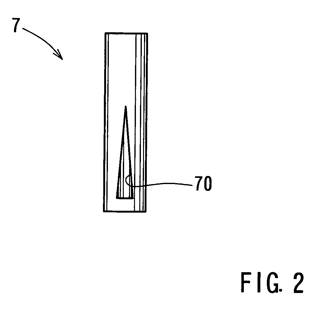
[0013]In order to permit and prevent communication between the first and second sub-chambers, the position of the orifice recess changes as the spool moves relative to the communication passage. In addition, because the orifice recess extends from the side of the first sub-chamber toward the side of the second chamber, the orifice recess may have a relatively simple configuration.
[0015]Therefore, as the orifice recess moves together with the spool relative to the second sub-chamber, the one end of the orifice recess having the diminishing cross-sectional area moves into and out of the second sub-chamber. The cross-sectional area of the orifice recess changes along its length (decreasing toward the second sub-chamber), therefore the flow rate of the working liquid flowing through the orifice recess can be gradually increased and decreased as the spool respectively moves toward the second sub-chamber and toward the first sub-chamber. As a result, the flow rate of the working liquid flowing through the orifice recess and the resulting pressure within the second sub-chamber can be finely adjusted so as to reliably reduce the pulsation pressure on the side of the master cylinder.

Problems solved by technology

However, the reciprocating pump may produce a pulsation in pressure as the working liquid is discharged from the pump.
When such pulsation (pressure variation) is produced, various pipelines as well as the master cylinder of the brake device may vibrate and possibly generate noises.
However, it has been difficult to sufficiently reduce the pulsation by merely incorporating a buffer chamber.

Method used


Image

  • Brake devices
  • Brake devices
  • Brake devices

Examples


Embodiment Construction

[0021]Each of the additional features and teachings disclosed above and below may be utilized separately or in conjunction with other features and teachings to provide improved brake devices and methods of using such improved brake devices. Representative examples of the present invention, which examples utilize many of these additional features and teachings both separately and in conjunction with one another, will now be described in detail with reference to the attached drawings. This detailed description is merely intended to teach a person of skill in the art further details for practicing preferred aspects of the present teachings and is not intended to limit the scope of the invention. Only the claims define the scope of the claimed invention. Therefore, combinations of features and steps disclosed in the following detailed description may not be necessary to practice the invention in the broadest sense, and are instead taught merely to particularly describe representative ex...


PUM


Abstract

A brake device comprises a brake cylinder, a reservoir, a pump, a master cylinder, and a pulsation-reduction device. The reservoir serves to accumulate a working liquid discharged from the brake cylinder. The pump serves to pump the working liquid accumulated within the reservoir. The master cylinder serves to receive the working liquid discharged from the pump. The pulsation-reduction device comprises a valve device disposed in a communication channel connecting the downstream side of the pump and the master cylinder. The valve device comprises a spool disposed within the communication channel. The spool is movable along the communication channel in response to differences in pressure between the pump side of the communication channel and the master cylinder side of the communication channel. The movement of the spool operates to open and close at least a part of the communication channel.

Description

[0001]This application claims priority to Japanese patent application Ser. No. 2003-283994, the contents of which are incorporated herein by reference.BACKGROUND OF THE INVENTION[0002]1. Field of the Invention[0003]The present invention relates to brake devices, and in particular to anti-lock brake devices having a pump operable to pump a working liquid. The pump transfers the working liquid from a reservoir to which the working liquid was previously discharged from a brake cylinder. The pump discharges the working liquid to the hydraulic circuit on the side of a master cylinder.[0004]2. Description of the Related Art[0005]In general, a brake device comprises a master cylinder and a brake cylinder. The master cylinder serves to supply a working liquid to a brake cylinder in response to the operation of a brake pedal. The pressure of the working liquid operates the brake cylinder in order to press a brake pad(s) against a braking surface. Brake devices are known that incorporate an a...

Claims


Application Information

Patent Timeline
Patent Type & Authority Patents(United States)
IPC IPC(8): B60T17/04B60T8/40B60T8/48B60T8/42B60T13/14B60T13/68
CPCB60T8/4068B60T8/4291B60T17/04B60T13/686B60T13/142
Inventor KONDO, MASUHIRO
Owner ADVICS CO LTD
Why Eureka
Try Eureka