Self-monitoring composite vessel for high pressure media

a composite vessel and high pressure technology, applied in the direction of rigid pipes, vessel walls, vessel geometry/arrangement/size, etc., can solve the problems of gas loss, additional parts that need to be fixed, extra cost and fabrication steps, etc., and achieve the effect of a greater safety margin

Active Publication Date: 2017-04-11
BELENOS CLEAN POWER HLDG
View PDF22 Cites 0 Cited by
  • Summary
  • Abstract
  • Description
  • Claims
  • Application Information

AI Technical Summary

Benefits of technology

[0009]It is therefore the main object of the present invention to provide an improved method for monitoring the pressure inside a high pressure media storage vessel through the development of a self-sensing liner combining high barrier performance.
[0014]To cope with the aforesaid objectives, liner materials exhibiting both excellent barrier and piezoelectric effects will be employed. Materials fulfilling this requirement include, but are not limited to PVdF and its copolymers, and composites of polymer containing piezoelectric ceramics such as PZT or barium titanate. Such materials will be henceforth referred to as ‘liner materials’. These materials display the combined qualities of acting as a good barrier layer, with the added advantage of the piezoelectric effect allowing real time monitoring of pressure and / or temperature to be made. The high sensitivity of piezoelectric materials enables small variations in pressure to be detected. As the liner itself provides the sensing element for the vessel, continuous monitoring of the vessel condition is possible, leading to earlier detection of leakage, including minute leaks from sub-critical flaws, and hence added safety.
[0015]Barrier properties may be further improved by the modification or treatment of the liner materials. Various techniques can be employed to achieve optimal liner barrier properties. These include the addition of nano-sized clay particles or other similar high aspect ratio particles which offer increased resistance to permeability, and improved mechanical properties. Additional layers may also be added to the liner materials in the form of coatings, deposited through a variety of processes from plasma deposition to metallization. Numerous coating layers may be deposited to obtain optimum liner properties, and these coatings may also bring additional functionalities such as acting as electrical contacts.
[0016]For a liner material to be incorporated into a vessel, it must have a hollow form, tubular for cylindrical vessels, or the same form as the desired shell shape for other structures. This can be achieved through various techniques, including rolling the liner material into a tube and welding the joint to make it leak-tight, or forming rolls, where the multiple layers overlap creating an airtight tube preventing loss of fluid from a joint. Closed forms can be made through blow molding with subsequently sealed ends, but depending upon the shell shape, the liner may require inserts at one or both ends to enable a sealed structure to be formed.
[0019]In addition to the self-sensing liner, which will provide internal monitoring of leakage, rather than a localized detection of leakage, strain sensors, such as optical fibres with Bragg grating sensors can be incorporated into the shell material to allow for an early detection of critical sized flaws and their corresponding location, which can be combined with the output from the piezoelectric liner to provide an even greater margin of safety at high pressure.

Problems solved by technology

For example gases in composite tanks (permeability levels of pure composite too high leading to gas loss) or hydrogen in steel vessels (possibility of embrittlement).
Drawbacks of existing technology for pressure sensing in vessels comprise the necessary requirements for additional parts to be fixed postproduction, involving extra costs and fabrication steps.
In addition, most pressure gauges are fitted to the tank only during service, so during storage and / or transportation phases, the pressure level in the tank is often unknown.
An externally mounted pressure gauge is unlikely to have the sensitivity to detect minute leaks in a vessel due to the initiation of sub-critical flaws in the tank or liner structure unless it has been specifically designed to do so, which is costly.

Method used


Image

  • Self-monitoring composite vessel for high pressure media
  • Self-monitoring composite vessel for high pressure media
  • Self-monitoring composite vessel for high pressure media

Examples


Embodiment Construction

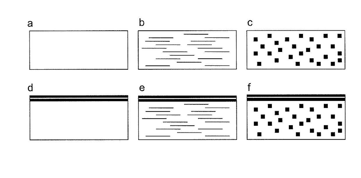
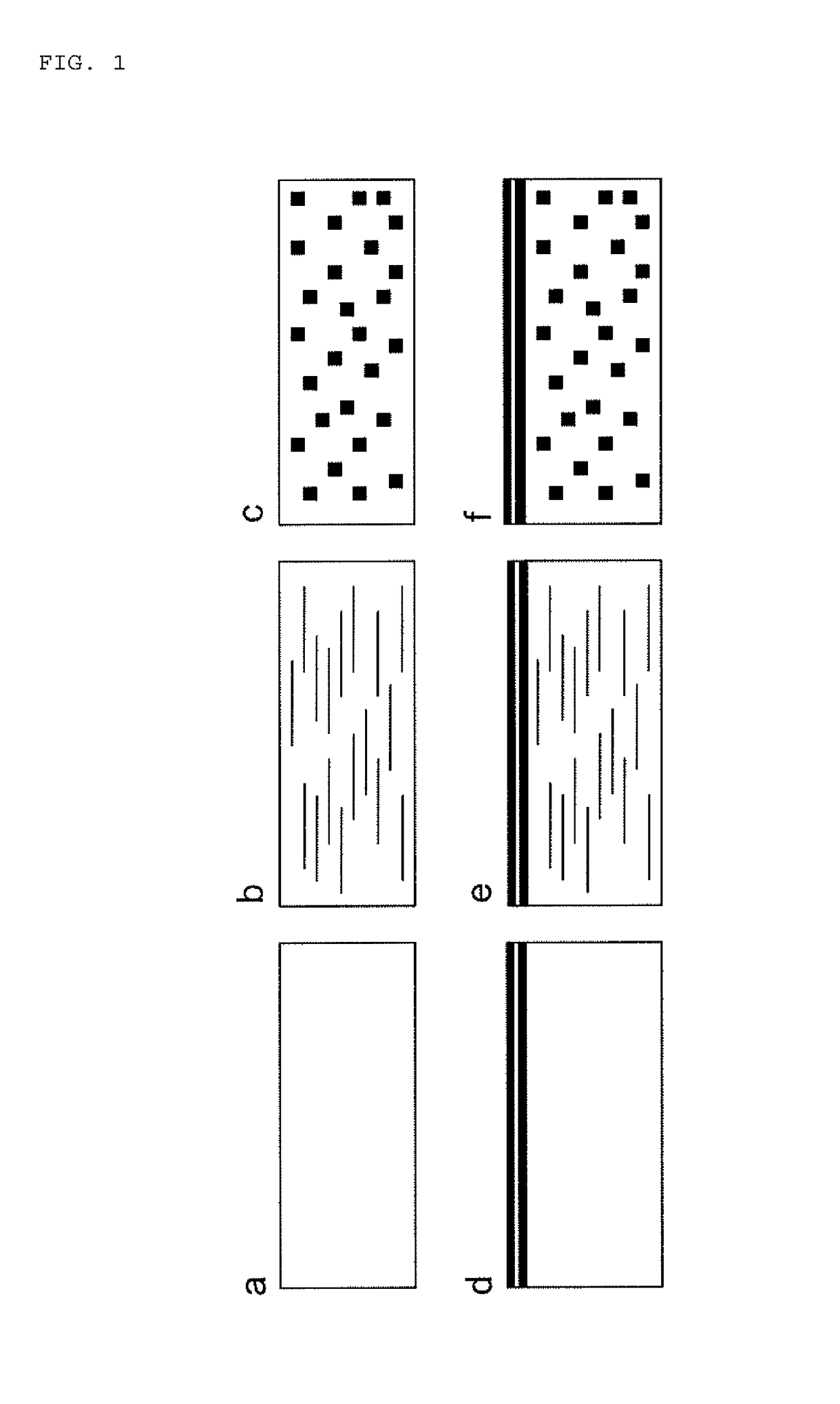
[0032]FIG. 1 shows preferred embodiments for the liner material construction. Six examples of possible liner material combinations are given. For each of the following descriptions, ‘polymer’ refers to polymer or copolymer material. In FIG. 1a, a pure piezoelectric polymer film such as PVdF and its copolymers is depicted. In FIG. 1b a piezoelectric polymer matrix such as PVdF and copolymers of PVdF containing high aspect ratio particles, for instance high aspect ratio clay platelets is shown, as a method of improving mechanical properties and increasing resistance to permeation. FIG. 1c shows a polymer matrix containing piezoelectric ceramic particles such as PZT or barium titanate particles. In this case, the piezoelectric functionality is provided by the piezoelectric ceramics, and the majority of the barrier functionality is due to the polymer matrix. FIGS. 1d-f show the embodiments presented in FIGS. 1a, 1b and 1c with an additional multi-layer coating to enhance barrier propert...


PUM

PropertyMeasurementUnit
thickaaaaaaaaaa
thickaaaaaaaaaa
thicknessaaaaaaaaaa

Abstract

A high pressure media storage vessel including a wall made of at least one layer with barrier and piezoelectric properties.

Description

CROSS-REFERENCE TO RELATED APPLICATIONS[0001]This is a National Phase Application in the United States of International Patent Application PCT / EP 2011 / 052727 filed Feb. 24, 2011, which claims priority on International Patent PCT / IB2010 / 050800 of Feb. 24, 2010. The entire disclosures of the above patent applications are hereby incorporated by reference.FIELD OF THE INVENTION[0002]This invention relates to the field of barrier liners for the storage of high pressure media and more specifically, barrier liners with a self-sensing capability.BACKGROUND OF THE INVENTION[0003]Hollow structures, or pressure vessels, here referred to as ‘vessels’ such as those used to store fluids and gases, particularly under pressure, such as pressurized gas tanks are generally made from metals such as steel or aluminium, or from composite materials.[0004]Storage of certain media requires a barrier liner within the vessel to prevent loss or vessel structural damage. For example gases in composite tanks (p...

Claims


Application Information

Patent Timeline
Patent Type & Authority Patents(United States)
IPC IPC(8): G01R29/22G01L9/08G01R31/16G01R19/145G01R23/20
CPCG01L9/08F17C2201/0109F17C2203/0604F17C2203/066F17C2203/0607F17C2203/068F17C2203/0636F17C2203/0663F17C2209/219F17C2209/2127F17C2209/2145F17C2250/043F17C2270/0184F17C2270/0189F17C2270/07G01R19/145G01R23/20G01R31/16Y10T428/13Y10T428/131Y10T428/1379
Inventor MANSON, JAN-ANDERS EDVINLETERRIER, YVESWALLER, JUDITH
Owner BELENOS CLEAN POWER HLDG
Why Eureka
Try Eureka