Collector member, power generator, and method of manufacturing collector member for power generator
a technology of power generator and collector member, which is applied in the manufacture of final products, electrochemical generators, cell components, etc., can solve the problems of reducing power generation performance, unable to achieve satisfactory performance, and inability to achieve high output, etc., and achieves high-performance power.
- Summary
- Abstract
- Description
- Claims
- Application Information
AI Technical Summary
Benefits of technology
Problems solved by technology
Method used
Image
Examples
first embodiment
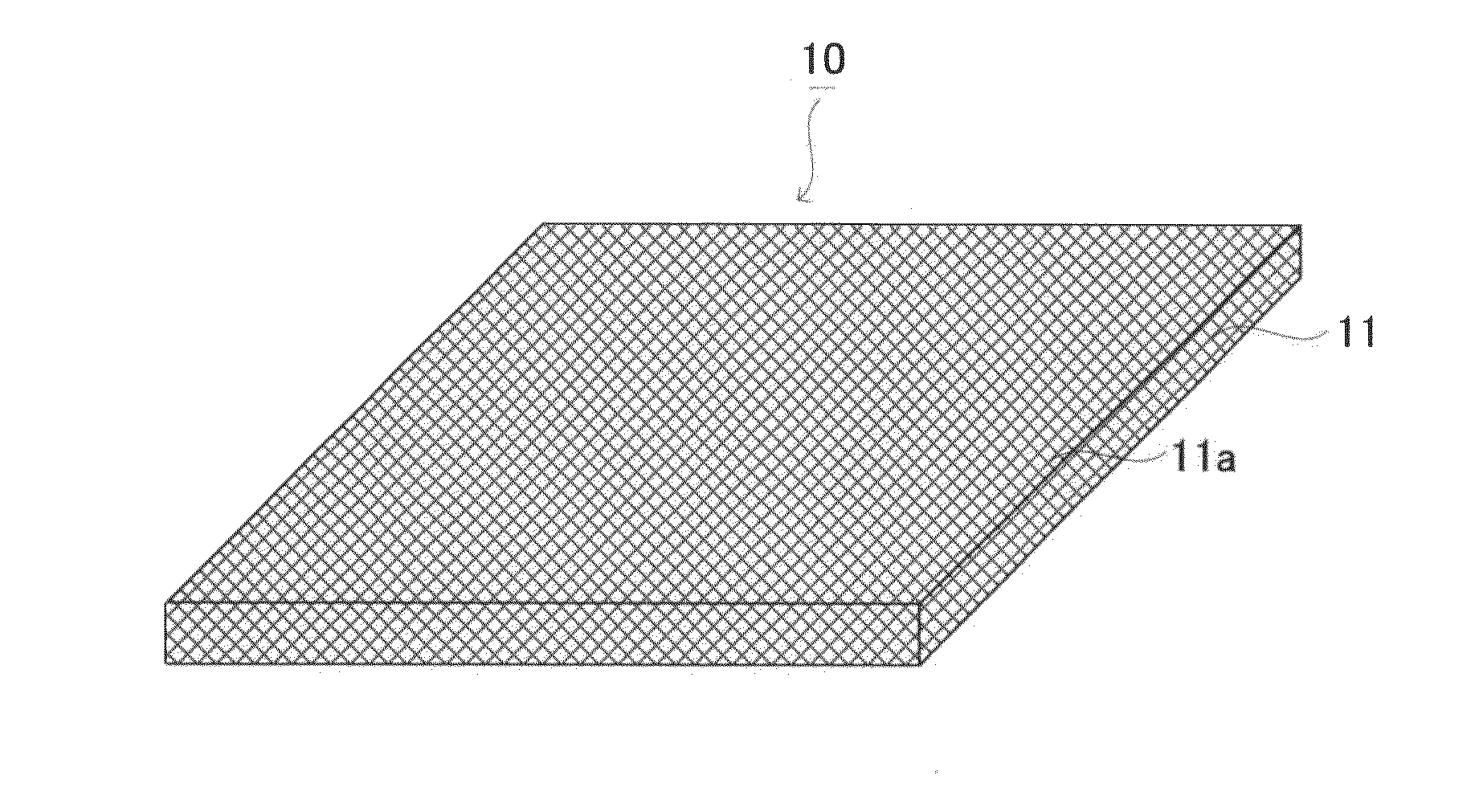
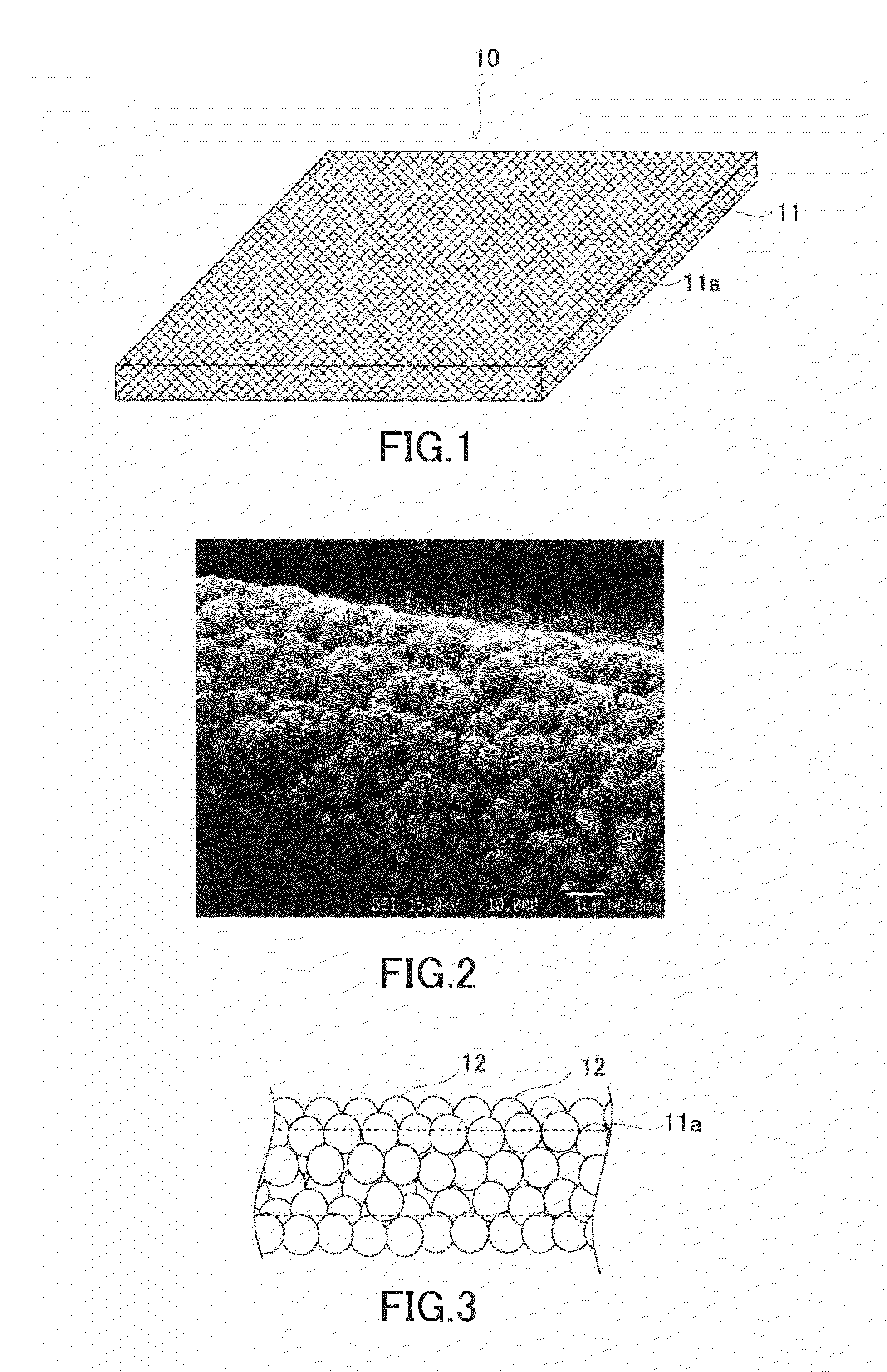
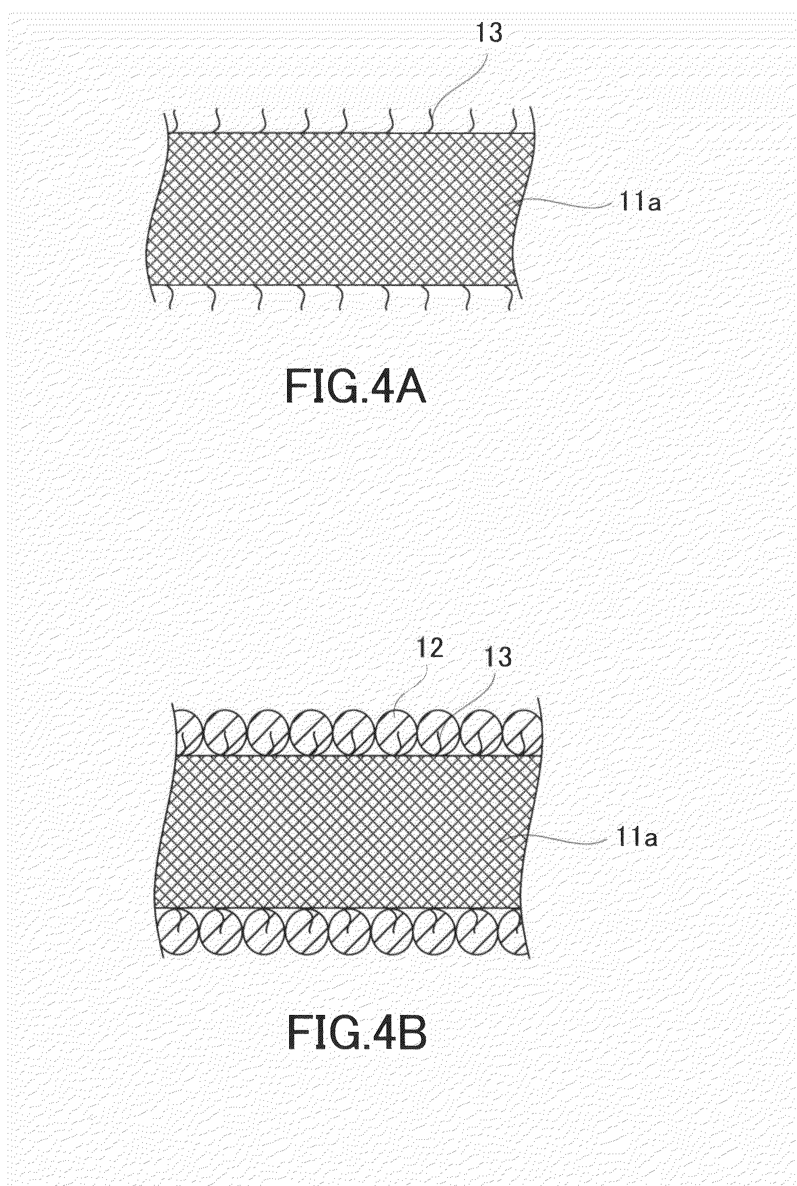
[0043]Hereinafter, a first embodiment of the present invention will be described with reference to the drawings. FIG. 1 is a view showing a schematic configuration of a collector member according to the present embodiment. FIG. 2 is a SEM photograph of the collector member according to the present embodiment. FIG. 3 is a partially enlarged view of the collector member according to the present embodiment.
[0044]As shown in FIGS. 1 to 3, a collector member 10 comprises a sheet-shaped base material 11 having a carbon-containing fiber 11a and catalyst particles 12 adhered to an outer periphery of the fiber 11a.
[0045]The sheet-shaped base material 11 is not limited especially as long as it has a carbon-containing fiber. Examples of the sheet-shaped base material 11 include a carbon paper. When the radius of the fiber 11a is r, it is preferable that an interval d between the fibers 11a in the sheet-shaped base material 11 satisfies the condition of r / 10<d<r / 3. This is because if the inter...
second embodiment
[0066]Hereinafter, a second embodiment of the present invention will be described with reference to the drawings. In the present embodiment, an example of a collector member having a carbon fiber layer between catalyst layers will be described. FIG. 8 is a view showing a schematic configuration of a collector member according to the present embodiment. FIG. 9 is a view showing a schematic configuration of another collector member according to the present embodiment.
[0067]As shown in FIG. 8, a collector member 30 is mainly constituted of an anode 31, a cathode 32, and a proton-conducting membrane 33 held by the anode 31 and the cathode 32. The collector member 30 functions as a membrane electrode assembly.
[0068]The anode 31 is constituted of a first catalyst layer 34, an intermediate layer 35 as a first intermediate layer, a second catalyst layer 36, and a sheet-shaped base material 37 stacked in this order. Namely, the intermediate layer 35 is interposed between the first catalyst l...
third embodiment
[0106]Hereinafter, a third embodiment of the present invention will be described with reference to the drawings. In the present embodiment, the description of the contents overlapped with those of the second embodiment is omitted, unless otherwise specified. In the present embodiment an example in which the thickness of the first catalyst layer and a second catalyst layer are different from each other will be described. FIG. 19 is a view showing a schematic configuration of a collector member according to the present embodiment.
[0107]As shown in FIG. 19, the thickness of a first catalyst layer 34 and the thickness of a second catalyst layer 36 are different from each other. Specifically, in FIG. 19, the thickness of the second catalyst layer 36 is larger than the thickness of the first catalyst layer 34.
[0108]According to the present embodiment, since the thickness of the first catalyst layer 34 and the thickness of the second catalyst layer 36 are different from each other, an effe...
PUM
| Property | Measurement | Unit |
|---|---|---|
| thickness | aaaaa | aaaaa |
| thickness | aaaaa | aaaaa |
| length | aaaaa | aaaaa |
Abstract
Description
Claims
Application Information
 - R&D
- Intellectual Property
- Life Sciences
- Materials
- Tech Scout
- Unparalleled Data Quality
- Higher Quality Content
- 60% Fewer Hallucinations
Browse by: Latest US Patents, China's latest patents, Technical Efficacy Thesaurus, Application Domain, Technology Topic, Popular Technical Reports.
© 2025 PatSnap. All rights reserved.Legal|Privacy policy|Modern Slavery Act Transparency Statement|Sitemap|About US| Contact US: help@patsnap.com


