Collector member, power generator, and method of manufacturing collector member for power generator

a technology of power generator and collector member, which is applied in the direction of cell components, final product manufacturing, sustainable manufacturing/processing, etc., can solve the problems of power generation performance reduction, unsatisfactory performance, and inability to achieve high output, etc., and achieve high-performance power

Inactive Publication Date: 2012-06-28
KK TOSHIBA
View PDF8 Cites 4 Cited by
  • Summary
  • Abstract
  • Description
  • Claims
  • Application Information

AI Technical Summary

Benefits of technology

[0019]According to the collector member according to an aspect of the present invention, the collector member according to another aspect, and the method of manufacturing a collector member for a power generator according to another aspect, a collector member having a highly active catalyst particles or catalyst layer can be provided. Further, according to the power generator according to another aspect of the present invention, a high-performance power generator can be provided.

Problems solved by technology

Since the catalyst obtained by being sputtered directly on the carbon paper is adhered as a film to a surface of a fiber constituting the carbon paper as shown in FIG. 21, an active surface area is small, and there is a problem that a high output cannot be obtained.
Although water is essential at an anode, if the catalyst layer is thin, the amount of water required for power generation cannot be held in the catalyst layer, so that a satisfactory performance may not be obtained.
Therefore, the surface area of the catalyst is small, and there is a problem that the power generation performance is reduced.
Consequently, since the effective catalyst adhesion area is reduced, a sufficient amount of catalyst cannot be supported, and a high power generation performance cannot be obtained.
Further, in the carbon fiber grown by the CVD method, since the mechanical strength and the adhesion strength with a base material are weak, there is such a problem that the catalyst is easily dropped in the process after the catalyst is physically evaporated.

Method used


Image

  • Collector member, power generator, and method of manufacturing collector member for power generator
  • Collector member, power generator, and method of manufacturing collector member for power generator
  • Collector member, power generator, and method of manufacturing collector member for power generator

Examples


first embodiment

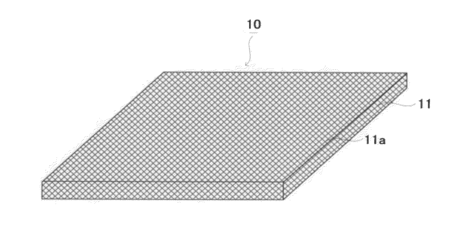
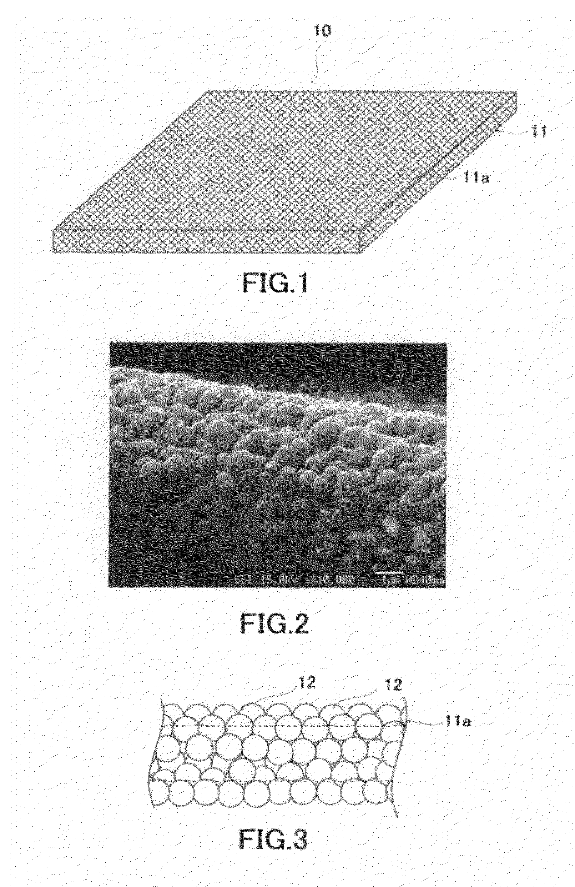
[0042]Hereinafter, a first embodiment of the present invention will be described with reference to the drawings. FIG. 1 is a view showing a schematic configuration of a collector member according to the present embodiment. FIG. 2 is a SEM photograph of the collector member according to the present embodiment. FIG. 3 is a partially enlarged view of the collector member according to the present embodiment.

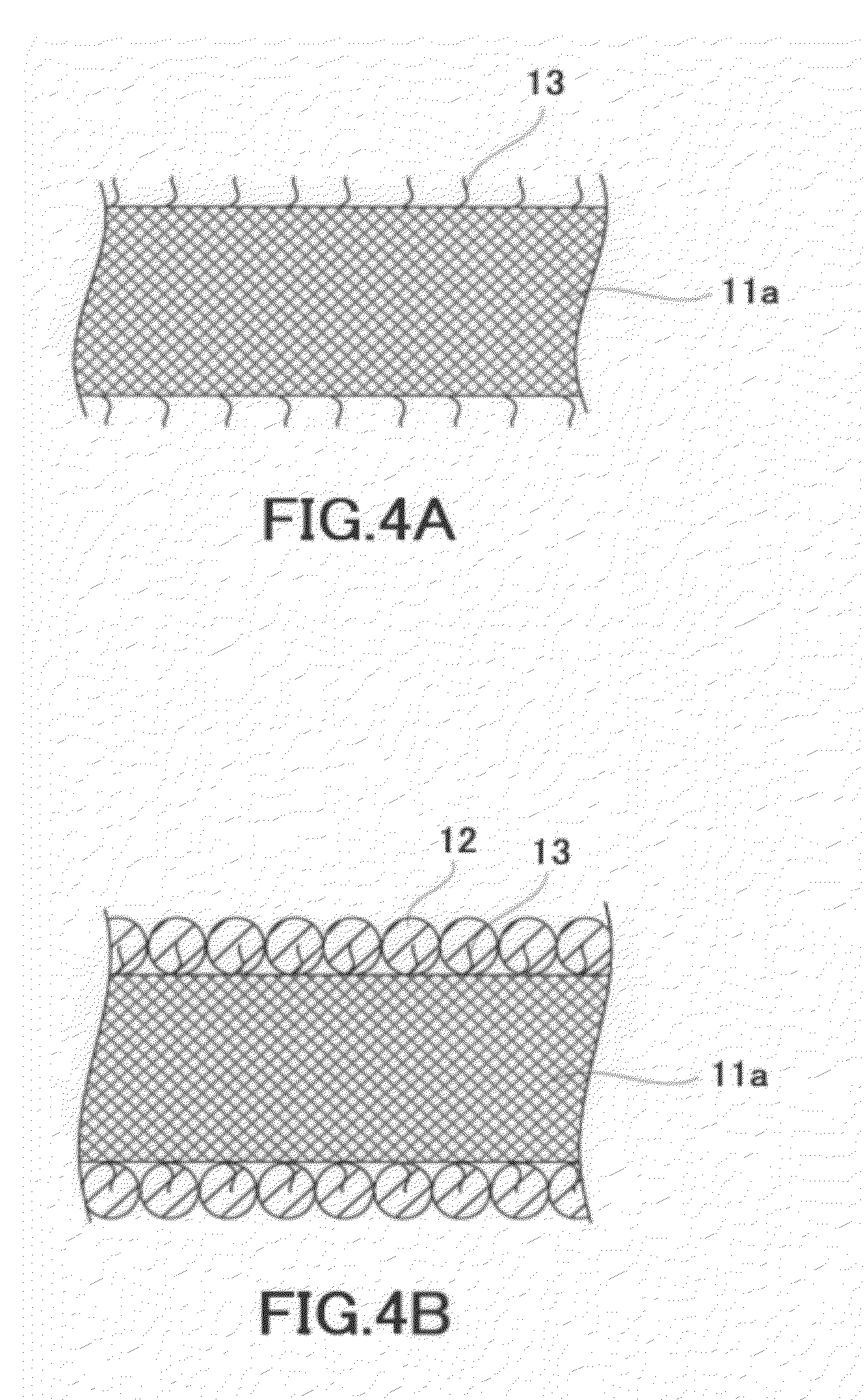
[0043]As shown in FIGS. 1 to 3, a collector member 10 comprises a sheet-shaped base material 11 having a carbon-containing fiber 11a and catalyst particles 12 adhered to an outer periphery of the fiber 11a.

[0044]The sheet-shaped base material 11 is not limited especially as long as it has a carbon-containing fiber. Examples of the sheet-shaped base material 11 include a carbon paper. When the radius of the fiber 11a is r, it is preferable that an interval d between the fibers 11a in the sheet-shaped base material 11 satisfies the condition of r / 10

second embodiment

[0065]Hereinafter, a second embodiment of the present invention will be described with reference to the drawings. In the present embodiment, an example of a collector member having a carbon fiber layer between catalyst layers will be described. FIG. 8 is a view showing a schematic configuration of a collector member according to the present embodiment. FIG. 9 is a view showing a schematic configuration of another collector member according to the present embodiment.

[0066]As shown in FIG. 8, a collector member 30 is mainly constituted of an anode 31, a cathode 32, and a proton-conducting membrane 33 held by the anode 31 and the cathode 32. The collector member 30 functions as a membrane electrode assembly.

[0067]The anode 31 is constituted of a first catalyst layer 34, an intermediate layer 35 as a first intermediate layer, a second catalyst layer 36, and a sheet-shaped base material 37 stacked in this order. Namely, the intermediate layer 35 is interposed between the first catalyst l...

third embodiment

[0103]Hereinafter, a third embodiment of the present invention will be described with reference to the drawings. In the present embodiment, the description of the contents overlapped with those of the second embodiment is omitted, unless otherwise specified. In the present embodiment an example in which the thickness of the first catalyst layer and a second catalyst layer are different from each other will be described. FIG. 19 is a view showing a schematic configuration of a collector member according to the present embodiment.

[0104]As shown in FIG. 19, the thickness of a first catalyst layer 34 and the thickness of a second catalyst layer 36 are different from each other. Specifically, in FIG. 19, the thickness of the second catalyst layer 36 is larger than the thickness of the first catalyst layer 34.

[0105]According to the present embodiment, since the thickness of the first catalyst layer 34 and the thickness of the second catalyst layer 36 are different from each other, an effe...


PUM

PropertyMeasurementUnit
particle diameteraaaaaaaaaa
lengthaaaaaaaaaa
particle diameteraaaaaaaaaa

Abstract

According to an aspect of the present invention, there is provided a collector member 10 comprising a sheet-shaped base material 11 having a carbon-containing fiber 11a and catalyst particles 12 adhered to an outer periphery of the fiber 11a, containing a noble metal or an alloy thereof, and having an average particle diameter of 0.1 to 2 μm.

Description

FIELD[0001]The present invention relates to a collector member, a power generator using the collector member, and a method of manufacturing a collector member for a power generator.BACKGROUND[0002]Noble metals such as Pt are used as chemical catalysts instead of being used in accessories. For example, the noble metals are used in an exhaust emission control system of a vehicle and a solid polymer fuel cell, for example. Particularly, a methanol type solid polymer fuel cell using a methanol solution as a fuel can be operated at low temperature, and, at the same time, since the size and weight are small, the methanol type solid polymer fuel cell has been actively studied recently for the purpose of being applied to a power supply of a mobile apparatus and the like.[0003]Thus, it has been considered to add other elements to PtRu for the purpose of improving methanol oxidation activity. In a solution technique such as a dipping method generally used in catalyst synthesis, a metal desire...

Claims


Application Information

Patent Timeline
Patent Type & Authority Applications(United States)
IPC IPC(8): H01M4/90H01M4/92B05D5/12H01M8/10
CPCH01M4/8605H01M4/921H01M4/926H01M4/8875H01M8/1002Y02E60/521H01M4/8871H01M8/0234H01M8/1007Y02E60/50Y02P70/50
Inventor YAMAZAKI, MUTSUKINAKANO, YOSHIHIKOMEI, WU
Owner KK TOSHIBA
Why Eureka
Try Eureka