
Bonded fluid heat exchanging apparatus

a technology of heat exchange apparatus and bonded fluid, which is applied in the direction of indirect heat exchangers, lighting and heating apparatus, laminated elements, etc., can solve the problems of obstructing the reduction of manufacturing costs and difficult work, and achieves high heat exchange efficiency, small volume of heat exchange apparatus, and high chemical potential

Inactive Publication Date: 2015-03-26
PHILTECH
View PDF8 Cites 0 Cited by
  • Summary
  • Abstract
  • Description
  • Claims
  • Application Information

AI Technical Summary

Benefits of technology

The present invention aims to provide an apparatus for efficient heating and cooling of fluid such as gas or liquid at a low cost. Specifically, the invention aims to create a flow path structure using a cutting process that is easy and cost-effective, without compromising the efficiency of the apparatus. By making the cutting process easier, the manufacturing cost can be reduced, which expands the potential industry for application of the heat exchanging apparatus.

Problems solved by technology

However, when the base body is made of such hard material as metal, it takes time to work a groove having a width of 1 mm, 2 mm or 3 mm and a depth of 2 mm, 3 mm or 5 mm deeply by using an end mill and it is not easy.
This cutting work obstructs reduction of a manufacturing cost.

Method used


Image

  • Bonded fluid heat exchanging apparatus
  • Bonded fluid heat exchanging apparatus
  • Bonded fluid heat exchanging apparatus

Examples


Embodiment Construction

[0077]A first example is shown in FIG. 4.

[0078]A bonded heat exchanging apparatus 400 is manufactured from a stainless steel sheet. A flow path sheet 401 with a flow path formed by applying die stamping to a stainless steel sheet is manufactured. A depth of a tab of the flow path is 5 mm, a width thereof is 5 mm and a length thereof is 5 cm. Buffer tabs 403 and 404 having the same depth and length as those of the tab and having a width of 15 mm are provided at both ends of the flow path, and they are provided with a fluid inlet 405 and a fluid outlet 406 made of stainless steel pipes of ¼ inches through welding. A width of a channel is 2 mm, a length thereof is 6 mm, and a depth thereof is 2 mm.

[0079]The above flow path sheet 401 and a sealing sheet 402 having a thickness of 2 mm are welded to each other to have air tightness. A flow path 407 serving as a flow path having air tightness is constituted of the flow path sheet 401 and the sealing sheet 402, so that the bonded heat chang...


PUM

PropertyMeasurementUnit
lengthaaaaaaaaaa
velocityaaaaaaaaaa
depthaaaaaaaaaa

Abstract

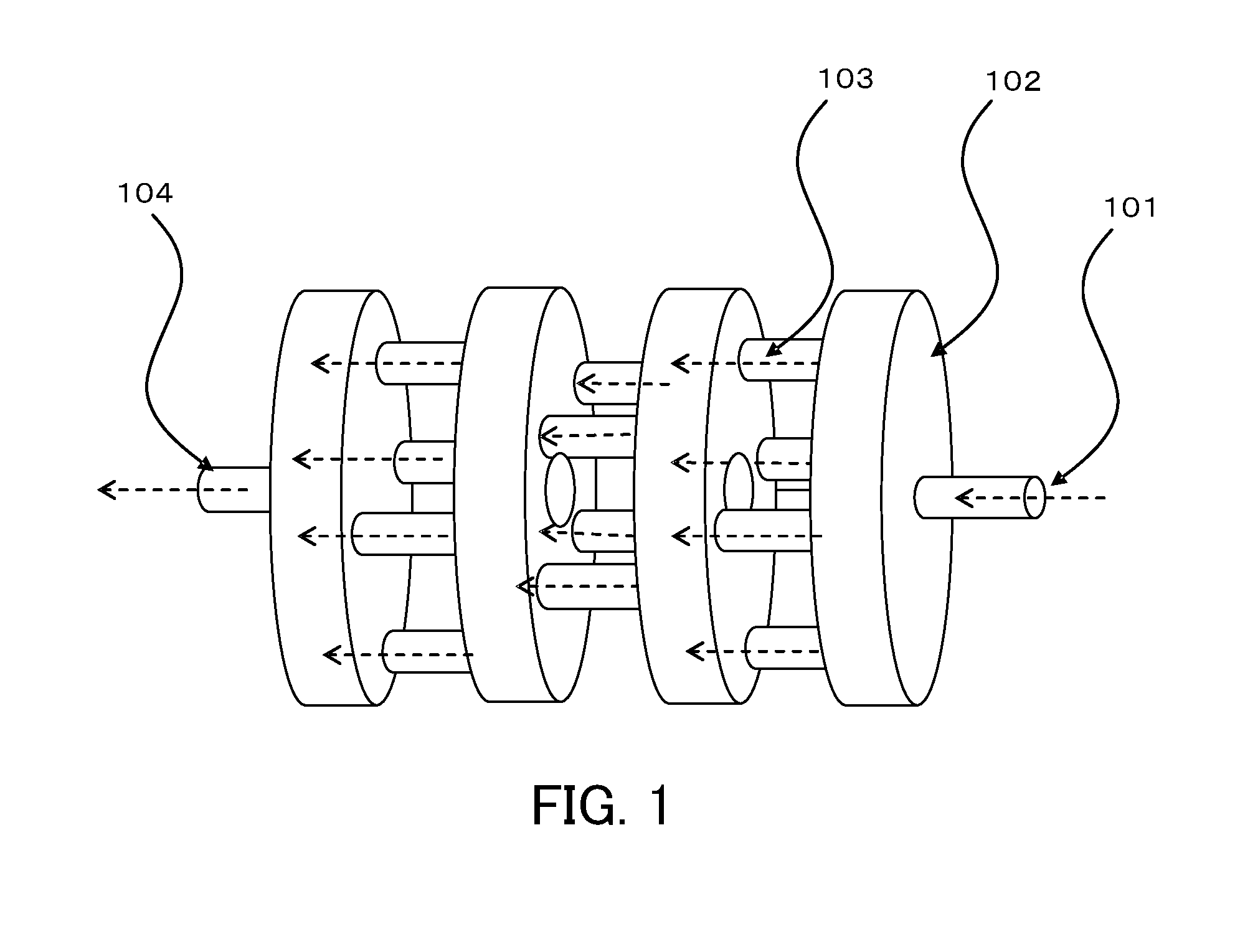
A heat exchanging apparatus has a flow path with air tightness formed by joining a second sheet to a first sheet formed by bending the first sheet by stamping and fluid introduced into the flow path impinges on a wall of the flow path to perform heat exchange. A material constituting the flow path may be a metal sheet or an electrically-conductive plastic, and a small-sized and light-weight heat exchanging apparatus can be manufactured at a low cost.

Description

BACKGROUND ART[0001]The present invention relates to a heat exchanging apparatus for heating or cooling fluid instantaneously.[0002]As a heat exchanging apparatus, for example, there is an apparatus for heating gas. A mechanism generally frequently used is a mechanism for heating gas by causing the gas to pass through a heated pipe. Alternatively, there is a mechanism for heating gas by causing heated fluid to a pipe with fins and causing the gas to pass through between the fins.[0003]These mechanisms are frequently used not only for gas but also to heat liquid or produce steam of water. An apparatus for cooling gas opposite to heating gas also has a similar mechanism.[0004]This structure is popular and has a history, but an apparatus having the structure requires a large volume. The reason is because efficiency of heat exchange between fluid flowing in a pipe and the pipe is poor.[0005]A mechanism having a popular structure for improving the heat exchange efficiency of the popular ...

Claims


Application Information

Patent Timeline
Patent Type & Authority Applications(United States)
IPC IPC(8): F28F3/12
CPCF28F3/12F28F13/18F28F19/02F28F21/083F28F21/089F28D7/106F28D9/0031F28F2255/08F28F2275/06F28D1/06F28D7/00F28D7/0008F28D7/0041F28D9/00F28D9/02F28F3/14F28F9/18F28F21/04
Inventor FURUMURA, YUJIMURA, NAOMINISHIHARA, SHINJISHIMIZU, NORIYOSHI
Owner PHILTECH
Learn More