Method of manufacturing a composite insert

Active Publication Date: 2015-03-26
HENKEL KGAA
View PDF4 Cites 3 Cited by
  • Summary
  • Abstract
  • Description
  • Claims
  • Application Information

AI Technical Summary

Benefits of technology

[0011]The subject method of manufacturing a composite insert significantly reduces the overall process cost, including cost for batch manufacturing, machinery and mold, as well as the development time required for production parts. In addition, by creating a composite part by over-molding the composite insert onto a carrier, manual processes for example fixing an insert to a carrier are eliminated at the final asse

Problems solved by technology

These prior art conditions require significant time and process control monitoring during manufacturing to maintain optimum equipment operating conditions and product quality.
Since high pressures are used, the molds, dies and other equipment used to injection mold or extrude under these conditions can be expensive.
Since extruded parts start out as strips of extruded

Method used


Image

  • Method of manufacturing a composite insert
  • Method of manufacturing a composite insert
  • Method of manufacturing a composite insert

Examples


Example

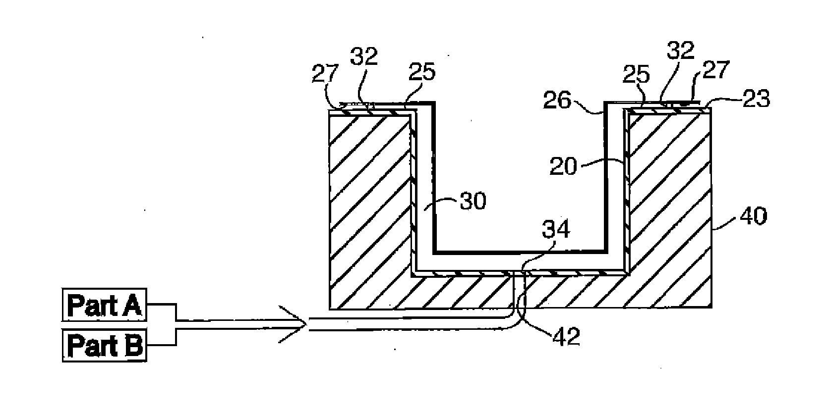
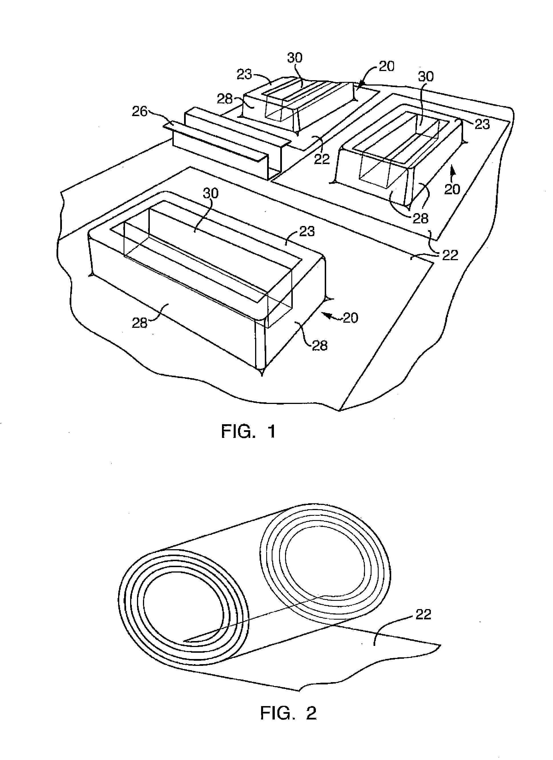
[0023]Referring to the Figures, wherein like numerals indicate corresponding parts throughout the several views, a method of manufacturing a composite insert, as well as a method of manufacturing a composite part including the composite insert and a carrier joined together, first includes a step of obtaining, forming or having formed (hereinafter referred to collectively as “forming”) a polymer mold 20 for use in manufacturing the composite insert. One example of a polymer mold 20 that may result from such a forming step is generally shown in FIG. 1. The polymer mold 20 of the embodiment shown in FIG. 1 comprises a cavity 30 for accepting a composite insert composition dispensed as a flowable or low pressure injectable material. Cavity 30 terminates at flange surfaces 23, which surround the cavity and extend outward therefrom. In this embodiment, the polymer mold 20 has external walls 28 and is self supporting.

[0024]The polymer mold 20 shown in FIG. 1 is only a generic embodiment of...


PUM

PropertyMeasurementUnit
Temperatureaaaaaaaaaa
Pressureaaaaaaaaaa

Abstract

A method of manufacturing a composite insert includes forming a polymer mold from a polymer sheet which may have a glass transition temperature of 70 to 160° C., the polymer mold either includes a cavity or may form a cavity disposed between the polymer mold and the carrier. The method proceeds by depositing a liquid reactive composite insert composition, which may be a two-component composition including a first part comprised of an isocyanate-epoxy blend and a second part comprised of an alcohol-epoxy blend, into the cavity under low pressure conditions of 0-10 bar and low temperature conditions of 15-100° C. The composition is then allowed to become dimensionally stable either within the polymer mold or between the polymer mold and the carrier.

Description

BACKGROUND OF THE INVENTION[0001]1. Field of the Invention[0002]A method of manufacturing a composite insert, useful as a structural and / or acoustic insert in a vehicle, as well as a method of manufacturing a composite part including the composite insert and a carrier, and inserts, parts and pre-packaged inserts and parts, made by these processes.[0003]2. Description of the Prior Art[0004]Traditional structural and acoustic inserts are manufactured from solid reactive compositions under high temperature and high pressure via injection molding or extrusion conditions. These prior art conditions require significant time and process control monitoring during manufacturing to maintain optimum equipment operating conditions and product quality. For example, since high temperature conditions are used, the temperatures of the equipment and the composition must be closely monitored to keep the reactive composition below its cure temperature. Due to the high heat input needed to make prior a...

Claims


Application Information

Patent Timeline
IPC IPC(8): B65D25/02B29C45/14B29C33/38
CPCB65D25/02B29C33/38B29L2031/30B29K2063/00B29C45/14B29C33/0016B29C33/40B29C45/14778B29L2031/3002B29C67/246B29C39/10B29C33/00B32B1/02Y10T428/1355Y10T428/1362Y10T428/1372Y10T428/1376
Inventor FLENER, MICHAEL J.HORNUNG, MARTINHUDINA, JOSEFKRUEGER, GREGORY A.
Owner HENKEL KGAA
Why Eureka
Try Eureka