Plane symmetric imaging optical plate

A technology of imaging optics and symmetry, applied in optics, optical components, instruments, etc., can solve the problems of high manufacturing cost, high processing technology requirements, inability to meet pixel requirements, etc., to reduce processing difficulty and overall cost, and reduce processing accuracy requirements. Effect

Pending Publication Date: 2017-09-15
陈科枫
View PDF4 Cites 3 Cited by
  • Summary
  • Abstract
  • Description
  • Claims
  • Application Information

AI Technical Summary

Problems solved by technology

[0003] However, the applicant found that the above-mentioned structure has a low pixel density and cannot meet higher pixel requirements because the light is directly imaged after the light is reflected by the concave unit optical element or the convex unit optical element. The processing technology of the convex unit optical element is high, so the manufacturing cost is relatively high, which is one of the reasons why the above structure has not been popularized.

Method used


Image

  • Plane symmetric imaging optical plate
  • Plane symmetric imaging optical plate
  • Plane symmetric imaging optical plate

Examples


Embodiment Construction

[0039] Embodiments of the present invention are described in detail below, and examples of the embodiments are shown in the drawings, wherein the same or similar reference numerals denote the same or similar elements or elements having the same or similar functions throughout. The embodiments described below by referring to the figures are exemplary and are intended to explain the present invention and should not be construed as limiting the present invention.

[0040] The plane symmetric imaging optical plate according to the present invention will be described in detail below with reference to the accompanying drawings.

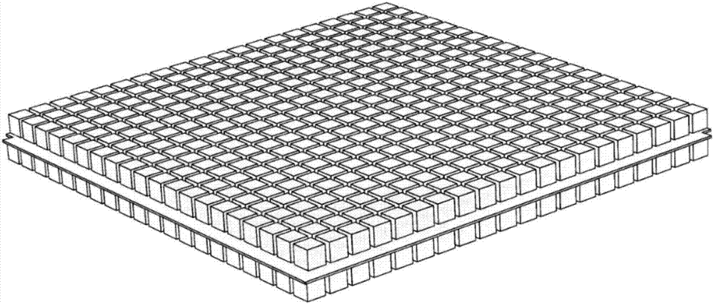
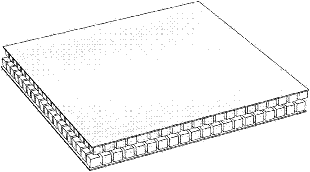
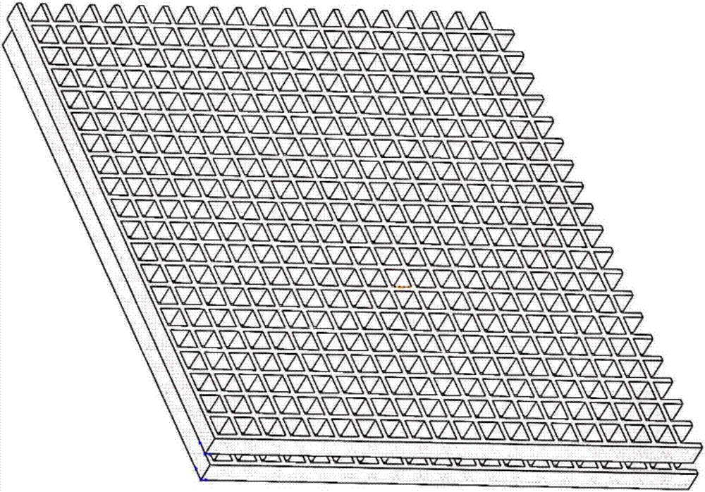
[0041] combined with Figure 1-19 As shown, the present embodiment is a plane symmetric imaging optical plate, including a first substrate above the first substrate and a second substrate below the first substrate, the first substrate and the second substrate are provided with a plurality of such as Figure 8-12 The first reflective surface and the second ...


PUM


Abstract

The invention provides a plane symmetric imaging optical plate. The plane symmetric imaging optical plate comprises a first light-permeable substrate and a second light-permeable substrate which are arranged from top to bottom, and is characterized in that the first substrate is provided with a plurality of first reflecting surfaces, the second substrate is provided with a plurality of second reflecting surfaces which are orthogonal with the first reflecting surfaces, and divergent light arrives at the part above the first substrate after being reflected by the first reflecting surfaces and the second reflecting surfaces and is collected and imaged in a space above the first substrate. The plane symmetric imaging optical plate realizes twice reflection through staggered rectangular blocks or rectangular holes arranged on the first substrate and the second substrate, and the pixel density is enabled to be higher than that of similar technologies. In addition, the plane symmetric imaging optical plate has a low requirement for the machining accuracy for right angles of the rectangular blocks or rectangular holes is low, light is reflected only through the side wall, and the machining difficulty and the overall cost are reduced.

Description

technical field [0001] The invention relates to the technical field of optical imaging components, in particular to a plane symmetrical imaging optical plate. Background technique [0002] The planar symmetric imaging optical elements in the prior art are mainly used in display devices, where the divergent light emitted by a luminous object or an optically irradiated object is transmitted through an optical plate, reflected twice in the optical plate, and then can be compared with the luminous object or The optical plate that optically irradiates the object has a positional relationship, and converges the image at a plane symmetrical position. Among them, the micromirror array formed by arranging a plurality of concave unit optical elements or convex unit optical elements in an array has attracted attention in recent years. The unit optical element or the convex unit optical element has "two mutually orthogonal mirror surfaces" (a pair of adjacent light reflection surfaces f...

Claims


Application Information

Patent Timeline
Patent Type & Authority Applications(China)
IPC IPC(8): G02B27/00
CPCG02B27/00
Inventor 陈科枫
Owner 陈科枫
Why Eureka
Try Eureka