Ultrasonic image processing apparatus

a processing apparatus and ultrasonic technology, applied in the field of ultrasonic image processing apparatus, can solve the problems of image blur, image shift or deformation in the beam scan direction, and the quality of the ultrasonic image cannot be sufficiently improved, so as to improve image quality, improve image quality, and increase the density of ultrasonic imag

Inactive Publication Date: 2012-05-17
HITACHI LTD
View PDF8 Cites 33 Cited by
  • Summary
  • Abstract
  • Description
  • Claims
  • Application Information

AI Technical Summary

Benefits of technology

[0009]An advantage of the present invention is that a density of an ultrasonic image is increased, to improve image quality.
[0010]Another advantage of the present invention is that, when a scanning method in which an ultrasonic beam array is formed in a fan shape or a radial shape is executed, image quality is improved in the ultrasonic image, in particular, in a deep portion of the image.
[0011]According to one aspect of the present invention, there is provided an ultrasonic image processing apparatus comprising an in-frame processor which applies a process between a first pixel array and a second pixel array in a frame acquired by transmitting and receiving ultrasound, and which calculates a movement destination on the second pixel array for each pixel of interest in the first pixel array, and a re-constructing unit which re-constructs the second pixel array into a high-density pixel array using the movement destination calculated for each pixel of interest.
[0012]With the above-described configuration, the density of the second pixel array can be increased using information in the first pixel array. In other words, because of continuity of the tissue on the beam scan plane, a local pixel value pattern observed on a certain pixel array and a local pixel value pattern observed on another pixel array nearby tend to be similar to each other. Therefore, the data of the former pixel array can be used to improve the latter pixel array. In particular, the method is preferably applied between two pixel arrays that are adjacent in space. By incorporating the content of a first pixel array into a second, adjacent pixel array, the resolution of the content of the second pixel array can be improved. With this process, for example, an outline and a boundary can be emphasized. More specifically, first, the in-frame process is used to calculate a movement destination (or corresponding position) on the second pixel array, for a plurality of pixels forming an entirety of or a part of the first pixel array. With this process, an additional group of pixels which are imaginarily or actually mapped can be defined or considered on the second pixel array. With the additional group of pixels, the pixel density of the second pixel array can be increased. The high-density pixel array may be re-constructed by simply adding the additional group of pixels to the original group of pixels of the second pixel array, or the high-density pixel array may be re-constructed by newly calculating a group of interpolation pixels using the original group of pixels and the additional group of pixels, and based on the original group of pixels and the group of interpolation pixels. In the former case, the original group of pixels (that is, the second pixel array) and the additional group of pixels may be handled without distinction, or, alternatively, the original group of pixels and the additional group of pixels may be managed separately in view of the convenience of the data process. For example, in the scan conversion of the frame, in addition to the original group of pixels, pixel values and movement destinations of pixels forming the entirety of or a part of the frame may also be considered.
[0013]With the above-described configuration, there can be created a situation as if the real pixel is increased on the pixel array can be created in place of simple increase of apparent number of pixels by the linear interpolation process, or a situation where the number or density of the real pixels referred to in the interpolation process is increased prior to the interpolation process. Therefore, a high-quality image with a high resolution can be formed, and problems such as blurring of the image can be effectively resolved or reduced.
[0014]The above-described ultrasonic image processing apparatus is, for example, an ultrasound diagnosis apparatus which executes ultrasound diagnosis in real time on a living body, or an information-processing device which processes data acquired in such an ultrasound diagnosis apparatus. The pixel on each frame is a frame element, and represents an echo intensity, Doppler information, etc. The density increasing process is preferably applied prior to the conversion from a transmission / reception coordinate system to a display coordinate system.

Problems solved by technology

However, in the related art, a simple linear interpolation process has been used as such interpolation processes, and, therefore, even though an amount of data appears to be increased, the quality of the ultrasonic image cannot be sufficiently improved.
Thus, in such a deep portion, although pixel insufficiency does not occur, there has been a problem in that the image is blurred.
More specifically, there has been a problem in that the image shifts or deforms in the beam scan direction.
A similar problem occurs when a three-dimensional image is formed.
In this case, however, the calculation during the scan conversion becomes complex, and, therefore, it is preferable to apply the scan conversion process after generating the high-density frame.

Method used


Image

  • Ultrasonic image processing apparatus
  • Ultrasonic image processing apparatus
  • Ultrasonic image processing apparatus

Examples


Embodiment Construction

[0058]Preferred embodiments of the present invention will now be described with reference to the drawings.

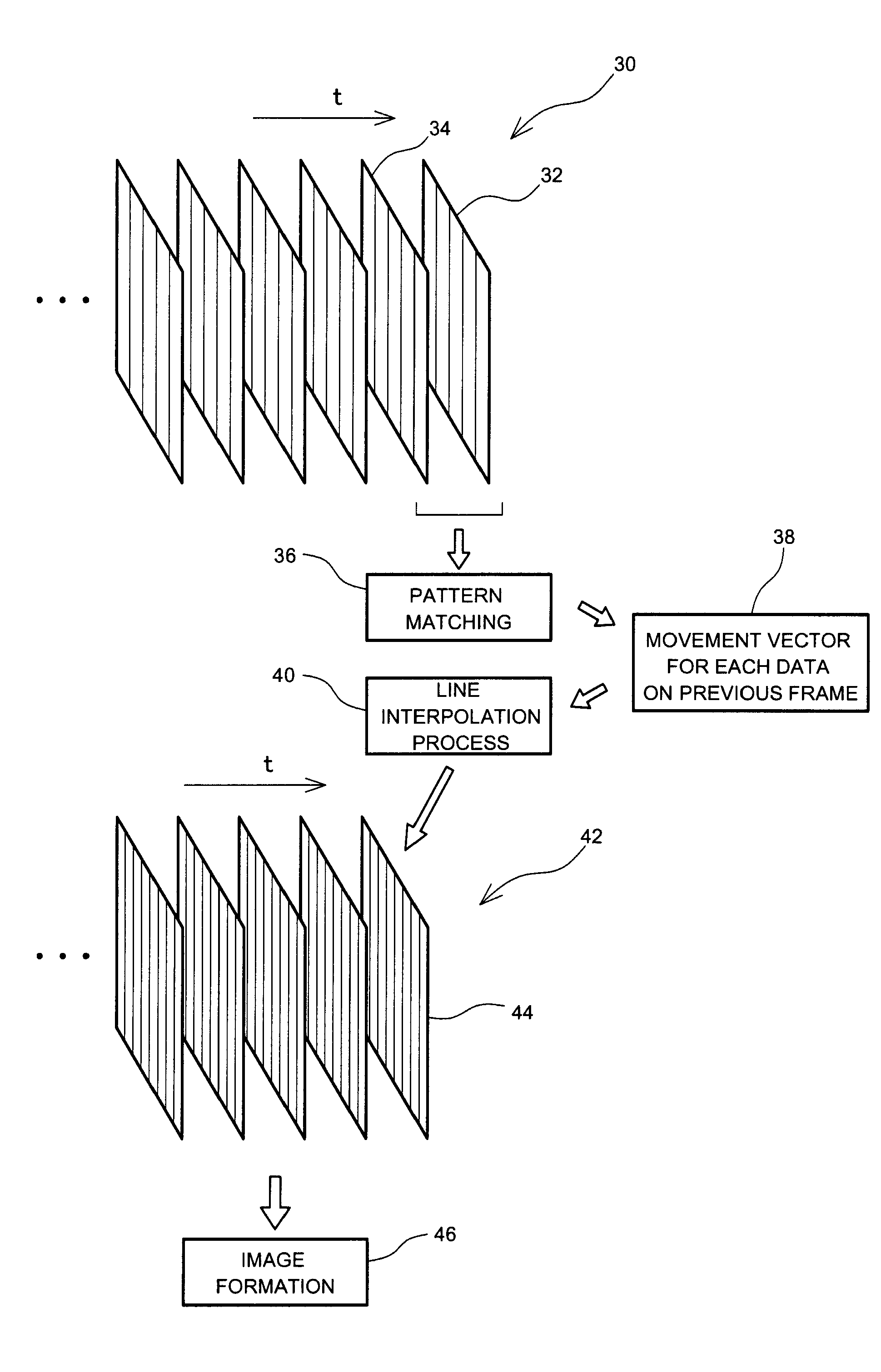
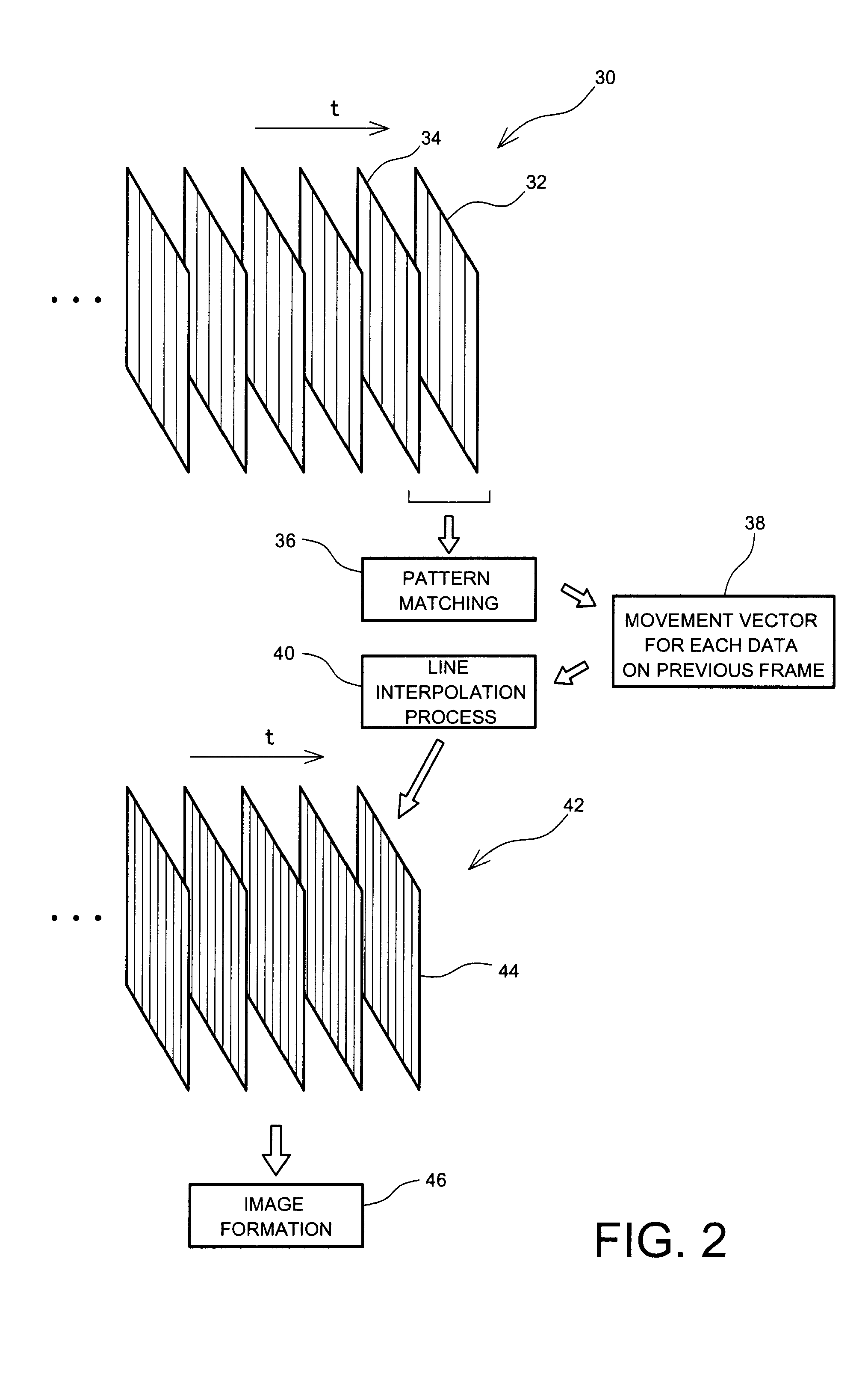
(1) Density Increasing using Inter-frame Pattern Matching Process

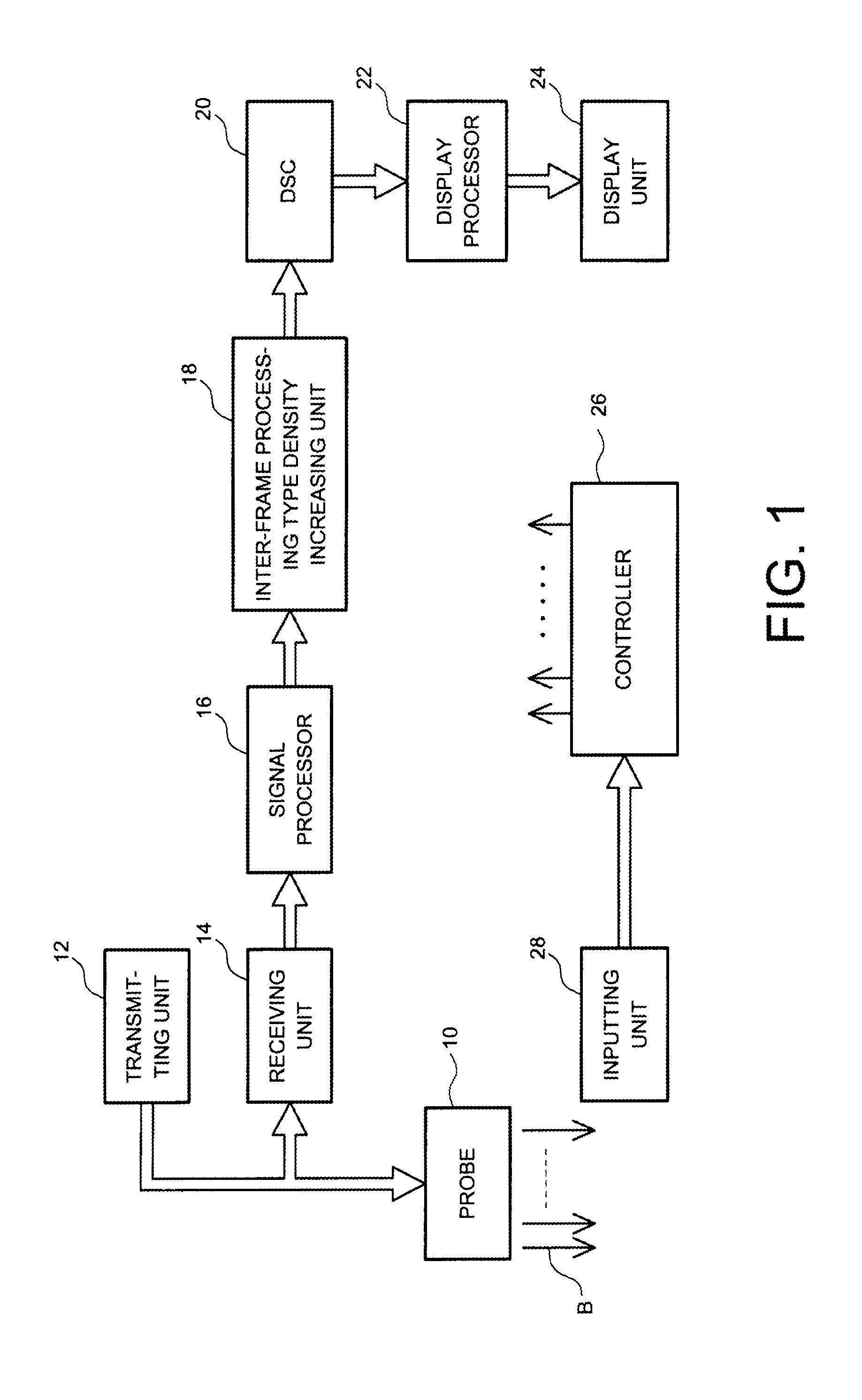
[0059]FIG. 1 is a block diagram showing an ultrasound diagnosis apparatus serving as an ultrasonic image processing apparatus. The ultrasound diagnosis apparatus is used in the medical field, and is an apparatus which forms an ultrasonic image based on a received signal which is acquired by transmitting and receiving ultrasound to and from a living body. As the ultrasonic image, a two-dimensional tomographic image, a two-dimensional bloodstream image, a three-dimensional image, etc. are known.

[0060]In an example configuration of FIG. 1, a probe 10 comprises a one-dimensional (1D) array transducer. The 1D array transducer comprises a plurality of transducer elements arranged in a straight line shape or an arc shape. An ultrasound beam B is formed by the 1D array transducer, and the ultrasound beam B is electrically ...


PUM


Abstract

There is provided an ultrasound image processing apparatus which displays an ultrasonic image with a higher resolution. In a received frame, a first pixel array, a second pixel array, and a third pixel array are defined in depths different from each other. For each pixel of interest on the first pixel array, a pattern matching process is applied between the first pixel array and the second pixel array, to calculate a mapping address on the second pixel array for the pixel of interest. In addition, for each pixel of interest on the third pixel array, a pattern matching process is applied between the third pixel array and the second pixel array, to calculate a mapping address on the second pixel array for each pixel of interest. The second pixel array is re-constructed into a high-density pixel array using pixel values and mapping addresses of a plurality of pixels of interest.

Description

BACKGROUND[0001]1. Technical Field[0002]The present invention relates to an ultrasonic image processing apparatus, and in particular to a technique for improving resolution or quality of ultrasonic images.[0003]2. Background Art[0004]An ultrasonic image processing apparatus is formed, for example, as an ultrasound diagnosis apparatus or an information-processing device. In the information-processing device, image data provided from the ultrasound diagnosis apparatus are processed. In the following, an ultrasound diagnosis apparatus will be described. An ultrasound diagnosis apparatus is an apparatus which transmits and receives ultrasound to and from a living body, and which forms an ultrasonic image based on received information acquired by the transmission and reception of the ultrasound. As an ultrasonic image, a two-dimensional tomographic image, a two-dimensional bloodstream image, a three-dimensional image, or the like are known.[0005]More specifically, an imaginary scan plane...

Claims


Application Information

Patent Timeline
Patent Type & Authority Applications(United States)
IPC IPC(8): G06K9/00
CPCG06T2207/10132G06T3/4023
Inventor MURASHITA, MASARU
Owner HITACHI LTD
Why Eureka
Try Eureka