Light Reflector

Inactive Publication Date: 2007-09-20
FURUKAWA ELECTRIC CO LTD
View PDF4 Cites 4 Cited by
  • Summary
  • Abstract
  • Description
  • Claims
  • Application Information

AI Technical Summary

Benefits of technology

[0009] According to the present invention, deformation of a light reflector plate fabricated by forming a synthetic resin reflector

Problems solved by technology

However, the foregoing light reflector plate deformation prevention means had demerits in that it was difficult to make the light reflector

Method used


Image

  • Light Reflector
  • Light Reflector
  • Light Reflector

Examples


Example

Example 1

[0026] There is a foamed plastic light reflector sheet (for example, MCPET (registered trademark), manufactured by Furukawa Electric Co., Ltd) with a thickness of 1 mm and bubbles with a bubble diameter of 50 μm or less, which is a thermoplastic polyester extrusion sheet heated and foamed after impregnating with carbon dioxide gas under high pressure. In addition, there is a cyclopolyolefin foamed plastic light reflector film with a thickness of 0.5 mm and bubbles with a bubble diameter of 50 μm or less. When these light reflector sheet and film are incorporated as reflector plates for backlight of a liquid crystal display device, the following example can be given as an example for manufacturing a three-dimensional light reflector plate behind the fluorescent light which is to be the light source of the backlight.

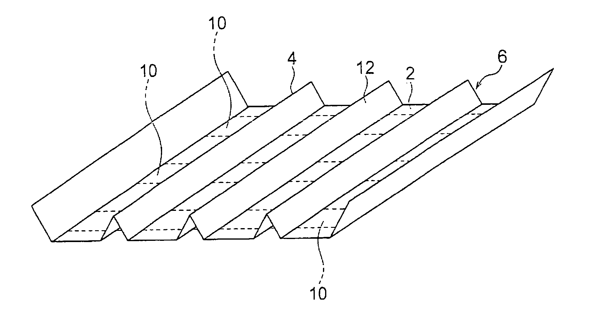
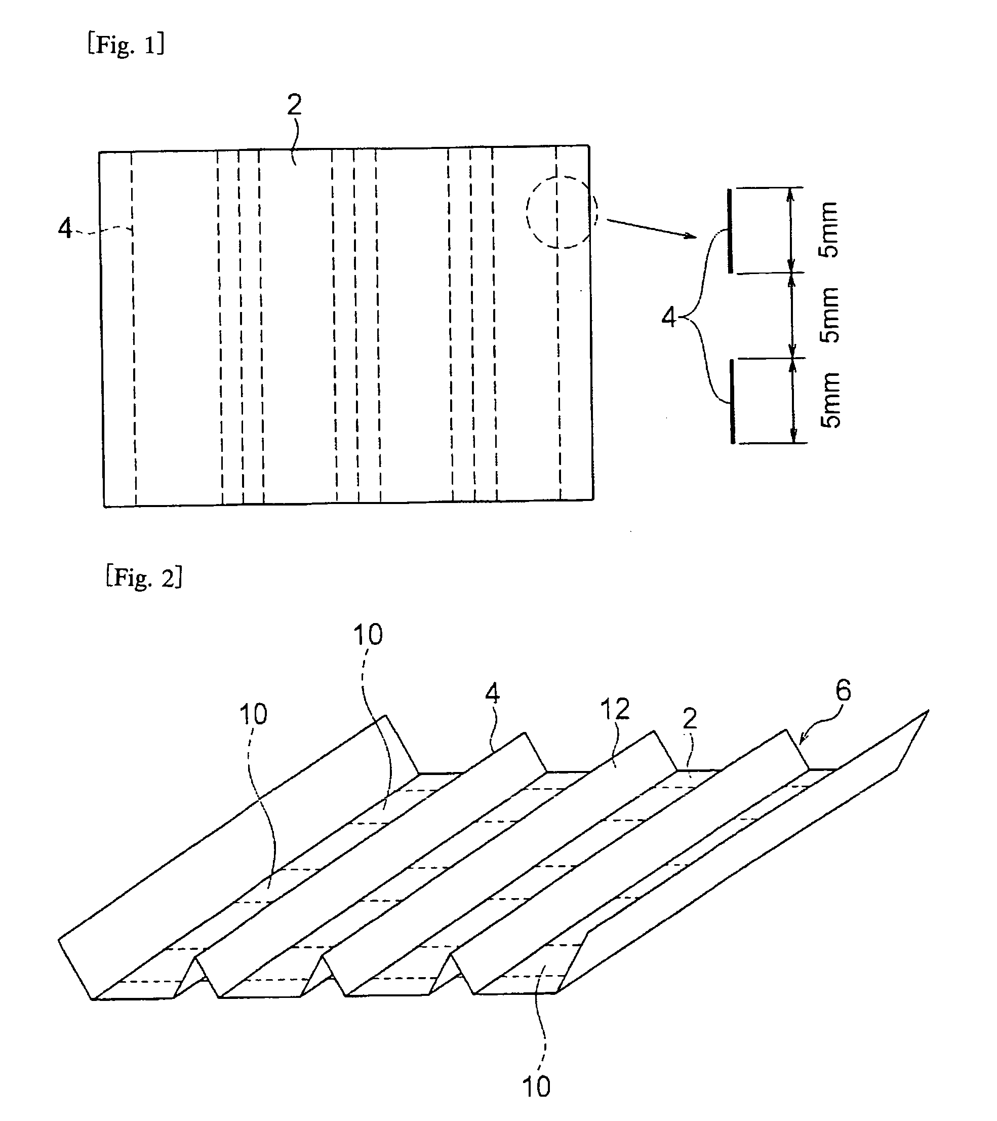
[0027] As shown in FIG. 1, perforations 4 were formed linearly using a band-blade press cutting blade with a blade thickness of 0.7 to 1.42 mm, for cutting perf...

Example

Example 2

[0030] The light reflector plate of the present invention was obtained in the same way as Example 1, aside from implementing a porous stretched sheet with a thickness of 0.25 mm, wherein numerous voids are formed with calcium carbonate as the core by stretching an un-stretched polyethylene terephthalate sheet containing calcium carbonate (filler), continuously forming a cut groove which does not penetrate the surface of the sheet on the sheet along a straight line, folding the sheet along this cut groove, and adhering adhesive tape to the entire back surface of the reflector plate. The light reflector plate of the present example has a plurality of mountain-shaped protrusion parts along the length direction of the strip light sources and the shape of the mountain-shaped protrusion parts is retained by the adhesive tape.

Example

Example 3

[0031] The light reflector plate of the present invention was obtained in the same way as Example 1, aside from implementing, as the light reflector sheet, a combined sheet wherein a porous stretched sheet with a thickness of 0.1 mm, wherein numerous voids are formed with calcium carbonate as the core by stretching an un-stretched polyethylene terephthalate sheet containing calcium carbonate (filler), is laminated with an aluminum sheet. An aluminum sheet was laminated onto this combined sheet because the porous, stretched polyethylene terephthalate sheet is thin, has no independence, and cannot retain a three-dimensional shape alone. The light reflector plate of the present example has a plurality of mountain-shaped protrusion parts along the length direction of the strip light sources and the shape of the mountain-shaped protrusion parts is retained by the adhesive tape.


PUM


Abstract

[PROBLEMS]A technology for effectively preventing deformation of a light reflector plate fabricated by forming a synthetic resin reflector plate into a three-dimensional shape enabling a thinner light reflector plate, and additionally, reducing processing costs is provided. [MEANS FOR SOLVING PROBLEMS]
An adhesive tape 10 for shape-retention is adhered onto a reflector plate 6 which is fabricated by forming predetermined areas of a light-reflecting plastic film or sheet 2 into a three-dimensional shape.

Description

TECHNICAL FIELD [0001] The present invention relates a three-dimensional light reflector plate enabling brighter and thinner backlights and illumination boxes for illumination signboards, liquid crystal display devices, lighting fixtures, and the like. BACKGROUND ART [0002] Conventionally proposed light reflector plates for use in illumination signboards, liquid crystal display devices, lighting fixtures, and the like, include those fabricated such that a synthetic resin reflector plate is formed into a three-dimensional shape to thereby yield a light reflector plate (refer to, for example, Patent Reference 1). [0003] Patent Reference 1: Japanese Patent Laid-Open Publication No. 2002-122863 DISCLOSURE OF THE INVENTION Problems to be Resolved by the Invention [0004] Deformation of the foregoing light reflector plate fabricated by forming a synthetic resin reflector plate into a three-dimensional shape occurs after manufacture due to strain during forming and shrinkage after forming....

Claims


Application Information

Patent Timeline
IPC IPC(8): G02B5/08C08J9/00F21V7/00F21V8/00
CPCG02B6/0031C08J9/00F21V7/00F21V7/10G02B5/08
Inventor SUZUKI, OSAMUNOUSOU, YOSHIYUKIMORITA, NOBUYUKINAGASHIMA, KAZUYA
Owner FURUKAWA ELECTRIC CO LTD
Why Eureka
Try Eureka