
Work vehicle chassis articulation joint

a technology for chassis and work vehicles, applied in the direction of other connections, transportation and packaging, trailer steering, etc., can solve the problems of affecting the construction of work vehicles in other aspects, articulation joints can interfere with the placement of drive shafts, and prior art articulation joints are generally complex and expensive to manufacture, so as to reduce or avoid clevis-connections, and reduce the complexity of articulation joints

Inactive Publication Date: 2015-03-26
DEERE & CO
View PDF27 Cites 4 Cited by
  • Summary
  • Abstract
  • Description
  • Claims
  • Application Information

AI Technical Summary

Benefits of technology

The patent reduces complexity in articulated chassis work vehicles by using a single lug or tab-like structure to connect the upper and lower joint assemblies, which avoids the need for more lug and bearing components. The technical effect is a simpler and more efficient design that saves space within the articulation joint.

Problems solved by technology

For one thing, the prior art articulation joints are generally complex and costly to manufacturing due to the number of components involved.
Clevis-type joints of this kind also can significantly affect the construction of the work vehicle in other aspects.
Consequently, the articulation joint can interfere with the placement of drive shafts, and electrical or plumbing lines that extend between the engine and the work implement or other components carried by the engine and equipment frames.
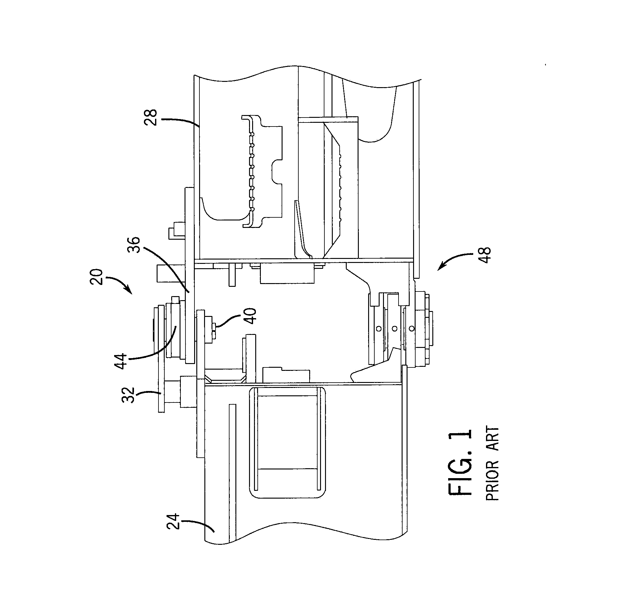
The double clevis-type connections of prior art articulation joints, such as shown in FIG. 1, are bulky and can significantly reduce the useable volume of space within the joint through which shafts and lines can be routed.
Often such interconnecting components must be routed around the joint, which is less than optimal placement, can impede articulation, and leaves the lines vulnerable to damage or pinching as the chassis is articulated, or due to debris.
Thus, in light of these considerations it may not be practical, or even possible, to position and size the articulation joint as needed to accommodate the interconnecting components within and through the joint while also meeting the overall height and ground clearance requirements of the vehicle.
Furthermore, if the resulting height of the vehicle is raised, it can also have adverse affects on vehicle stability and operator access to the vehicle cabin.

Method used


Image

  • Work vehicle chassis articulation joint
  • Work vehicle chassis articulation joint
  • Work vehicle chassis articulation joint

Examples


Embodiment Construction

[0026]As shown in the accompanying figures of the drawings described above, the following describes one or more example constructions of an articulation joint for an articulated chassis work vehicle. Various modifications to the example construction(s) may be contemplated by one of skill in the art.

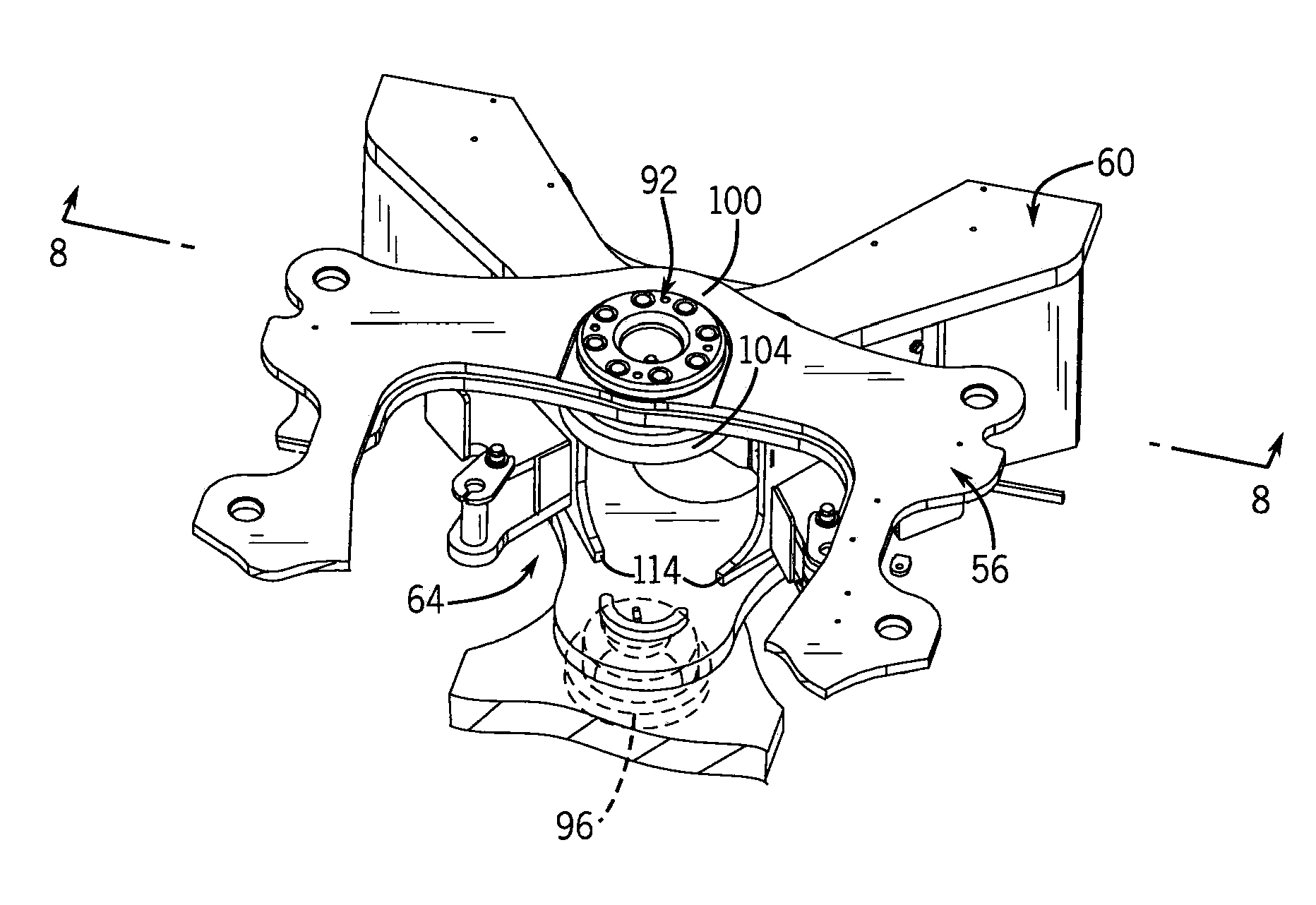
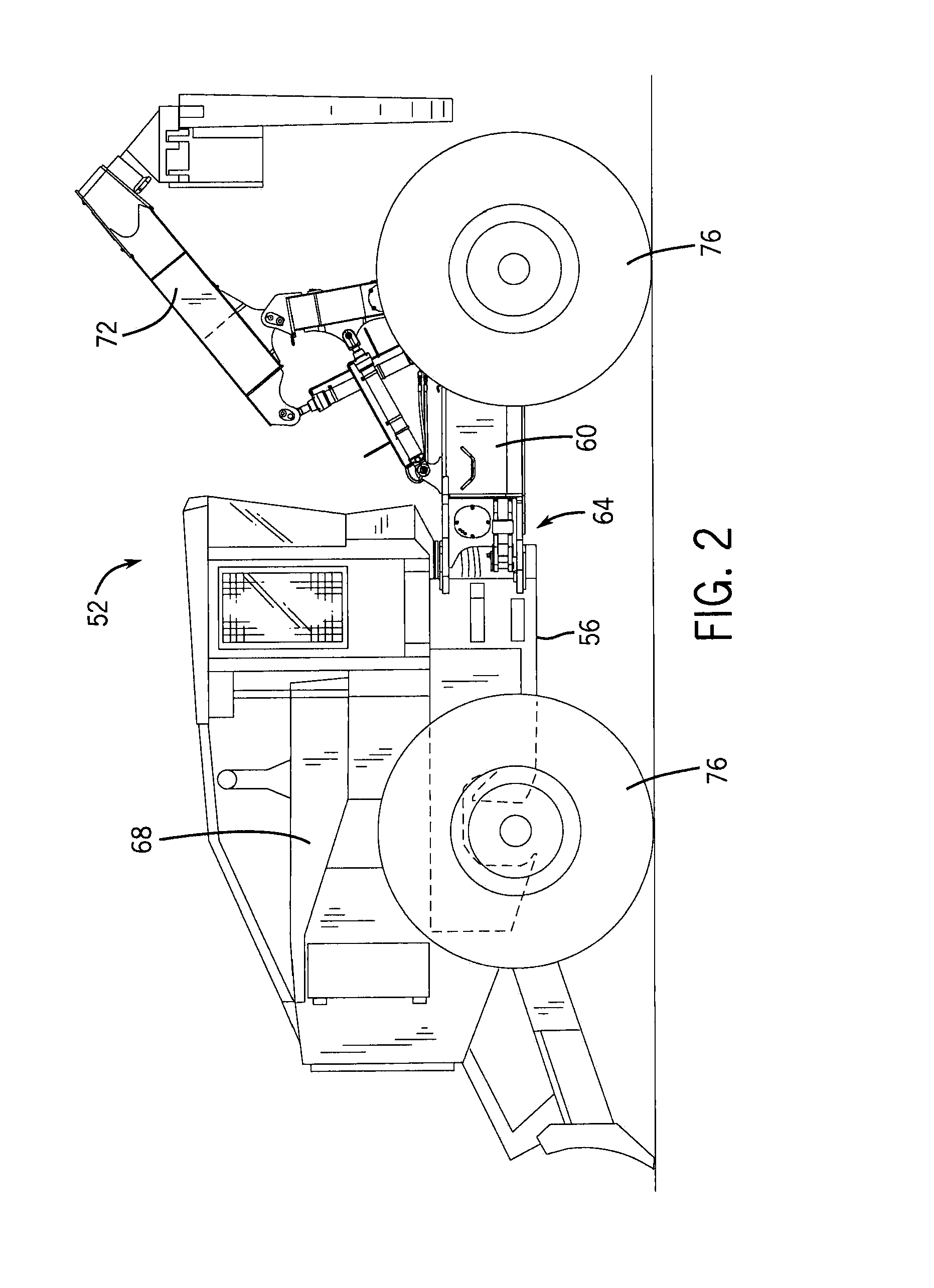
[0027]FIGS. 2 and 3 show an example work vehicle in the form of an articulated forestry vehicle 52, commonly called a “skidder”, that includes an articulated chassis formed by an engine frame 56 coupled to an equipment frame 60 by an example articulation joint 64. An engine 68 and other components are mounted to the engine frame 56, and a task specific implement 72, such as a boom-mounted grapple in the case of the illustrated skidder, is coupled to the equipment frame 60 and in communication with the engine 68. Four wheels 76 support the chassis of the forestry vehicle 52 and are coupled to drivetrain components driven by the engine 68 for movement over the ground. The articulation joint...


PUM


Abstract

An articulated chassis work vehicle has an articulation joint rotatably coupling separate engine and equipment frames of the vehicle chassis. The articulation joint can have upper and lower joint assemblies. One or both of the upper and lower joint assemblies are constructed and arranged so that a corresponding bearing assembly is located between a single tab-like lug of each frame. In one arrangement, the articulation joint does away with clevis connections at both the upper and lower joint assemblies such that the available space within the articulation joint defined between the innermost upper and lower lugs is not reduced by additional lug and bearing components of either joint assembly.

Description

CROSS-REFERENCE TO RELATED APPLICATION(S)[0001]Not applicable.STATEMENT OF FEDERALLY SPONSORED RESEARCH OR DEVELOPMENT[0002]Not applicable.FIELD OF THE DISCLOSURE[0003]This disclosure relates to articulation joints for articulated heavy duty work vehicles.BACKGROUND OF THE DISCLOSURE[0004]Many types of construction and forestry machines and other work vehicles have wide chasses and wheelbases, and consequently tend to track in a straight-ahead direction. To improve the cornering and turning capabilities of such large-bodied vehicles the chasses can be constructed with an articulation joint between separate front and rear frame sections. Typically, these articulated work vehicles include an engine frame that carries a prime mover, typically a gasoline or diesel engine, and an equipment frame that carries a task specific implement. The articulation joint connects the equipment frame to the engine frame and permits relative rotation of the chassis frames on the order of 90 degrees, suc...

Claims


Application Information

Patent Timeline
IPC IPC(8): B62D12/00B60D99/00
CPCB60D7/00B62D12/00B60D5/00B60D99/00
Inventor KUBOUSHEK, BRANDON J.BLASEN, STEVEN T.FICHTINGER, GARY RALPH
Owner DEERE & CO
Learn More