Al technical title is built by PatSnap Al team. It summarizes the technical point description of the patent document.
a technology of visualization system and surgical procedure, applied in the field of visualization system and display, can solve the problems of prolonged recovery time, scarring, pain, etc., and achieve the effect of smooth adjustment of viewing angl
Active Publication Date: 2015-03-26
CAMPLEX
View PDF4 Cites 48 Cited by
Summary
Abstract
Description
Claims
Application Information
AI Technical Summary
This helps you quickly interpret patents by identifying the three key elements:
Problems solved by technology
Method used
Benefits of technology
[0017]In some embodiments of the second aspect, the gimbal is configured to smoothly adjust the viewing angle of the auxiliary video camera between the first position and the second position. In some embodiments of the second aspect
Problems solved by technology
Open surgery is associated with significant drawbacks, however, as the relatively large incisions result in pain, scarring, and the risk of infecti
Method used
Image
Click on the blue label to locate the original text in one second.
Reading with bidirectional positioning of images and text.
Examples
embodiment
General Embodiment
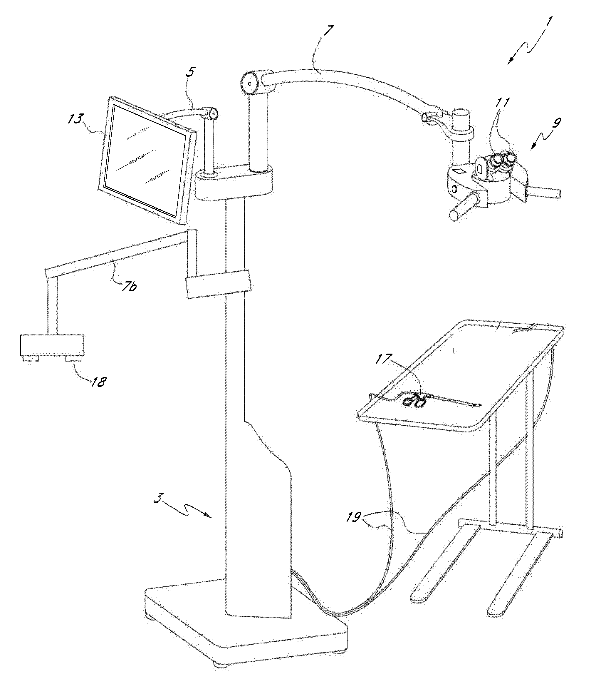
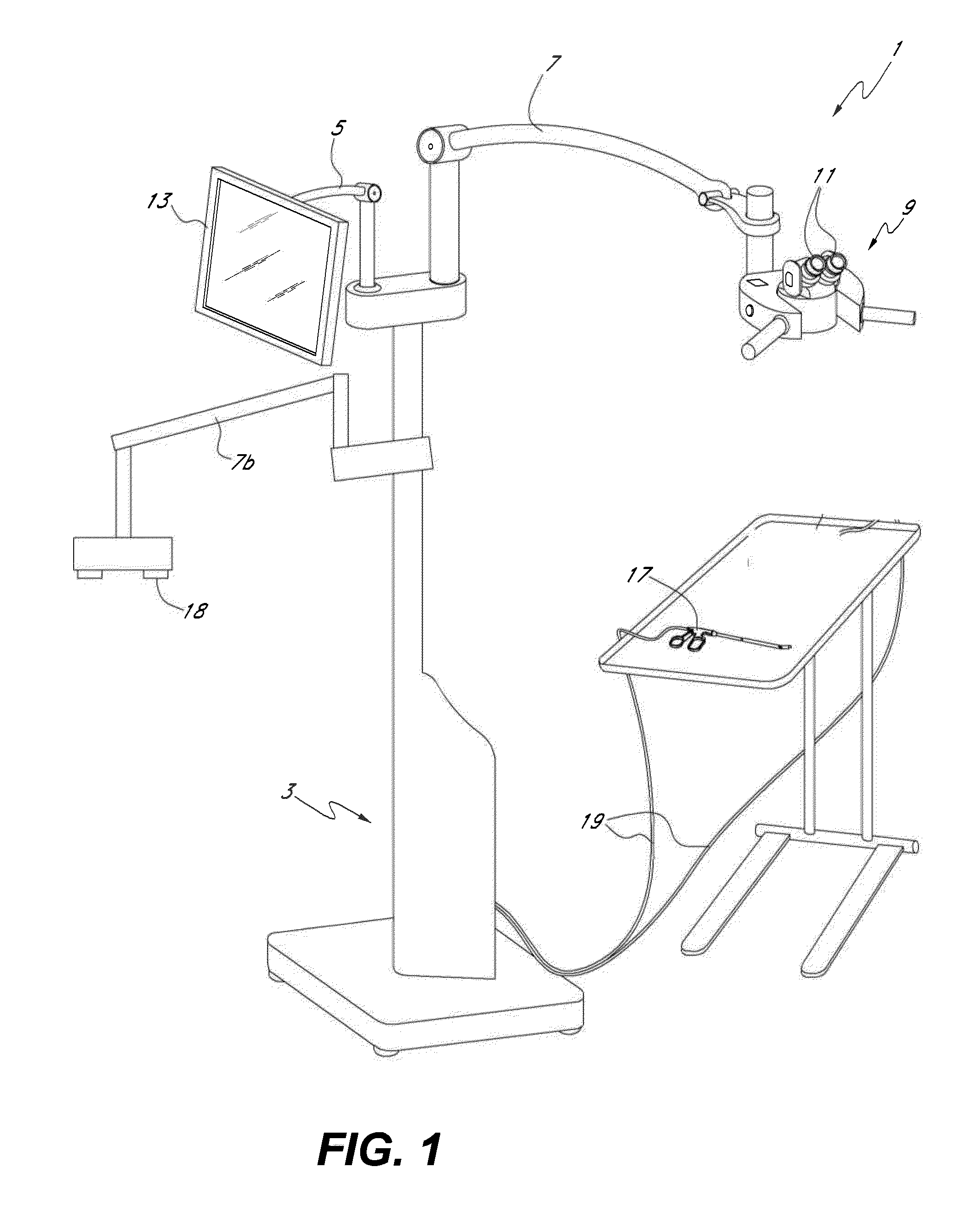
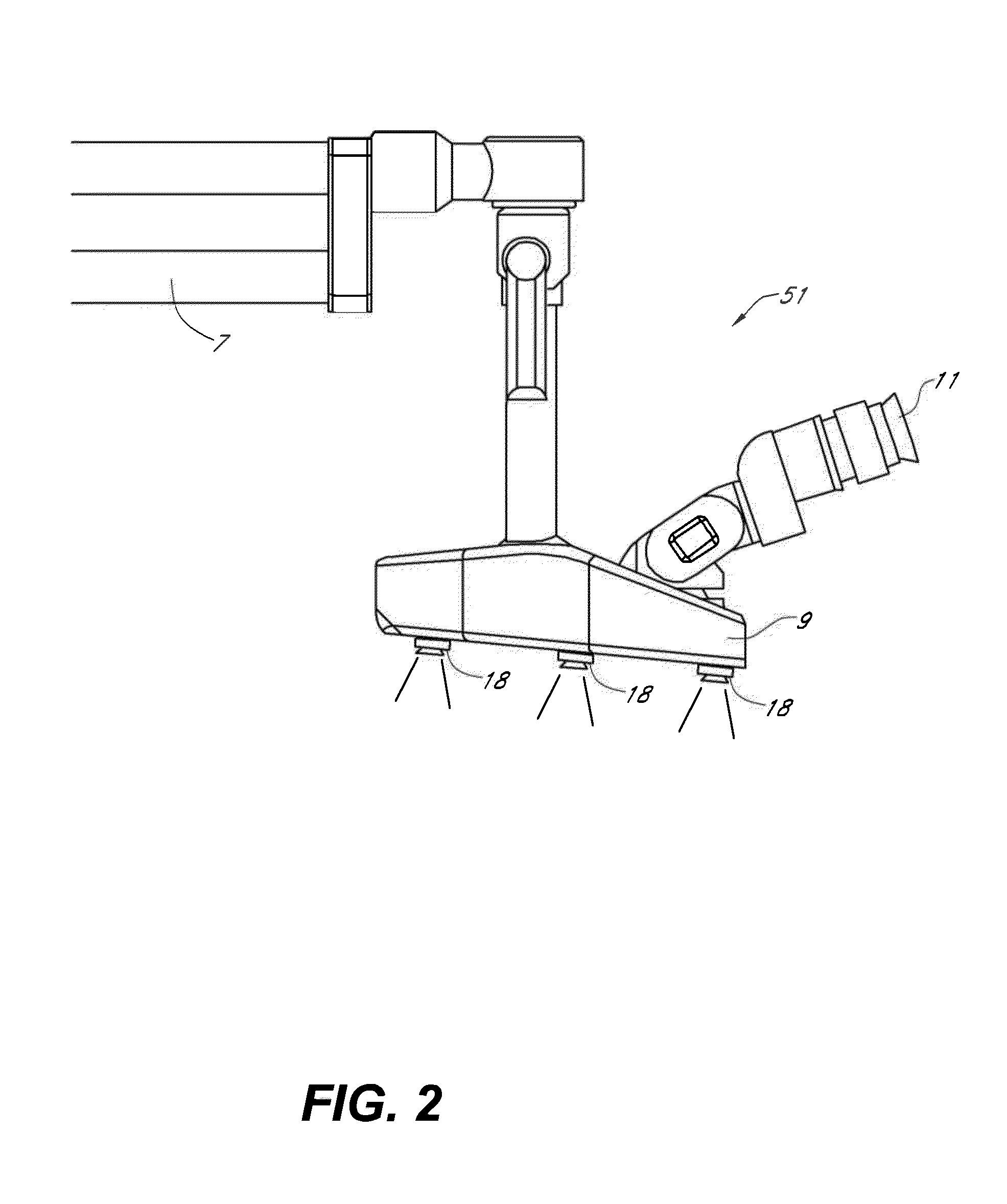
[0081]With continued reference to FIGS. 6A and 6B, in some embodiments, the movement control system 10100 can be attached to an attachment structure, such as binocular display unit 9, and support one or more imagers 18. As shown in the illustrated embodiment, the movement control system 10100 can be oriented generally underneath the binocular display unit 9 and in some embodiments can be sized such that the movement control system 10100 does not extend significantly beyond the outer housing of the binocular display unit 9. This can advantageously provide a smaller form factor thereby reducing the likelihood that the movement control system 10100 will interfere with the medical professionals and assistants during a medical procedure. In other embodiments, the attachment structure can be other components of the surgical visualization system 1 such as, but not limited to, a dedicated articulating arm or a display arm. In some embodiments, the movement control system 1...
PUM
Abstract
A medical apparatus is described for providing visualization of a surgical site. The medical apparatus includes an electronic display disposed within a display housing, the electronic display configured to produce a two-dimensional image. The medical apparatus includes a display optical system disposed within the display housing, the display optical system comprising a plurality of lens elements disposed along an optical path. The display optical system is configured to receive the two-dimensional image from the electronic display, produce a beam with a cross-section that remains substantially constant along the optical path, and produce a collimated beam exiting the opening in the display housing. The medical apparatus can also include an auxiliary video camera configured to provide an oblique view of a patient on the electronic display without requiring a surgeon to adjust their viewing angle through oculars viewing the electronic display.
Description
CROSS-REFERENCE TO RELATED APPLICATIONS[0001]This application claims the benefit of priority to U.S. Prov. App. No. 61 / 880,808, entitled “SURGICAL VISUALIZATION SYSTEMS”, filed Sep. 20, 2013; to U.S. Prov. App. No. 61 / 920,451, entitled “SURGICAL VISUALIZATION SYSTEMS”, filed Dec. 23, 2013; to U.S. Prov. App. No. 61 / 921,051, entitled “SURGICAL VISUALIZATION SYSTEMS”, filed Dec. 26, 2013; to U.S. Prov. App. No. 61 / 921,389, entitled “SURGICAL VISUALIZATION SYSTEMS”, filed Dec. 27, 2013; to U.S. Prov. App. No. 61 / 922,068, entitled “SURGICAL VISUALIZATION SYSTEMS”, filed Dec. 30, 2013; and to U.S. Prov. App. No. 61 / 923,188, entitled “SURGICAL VISUALIZATION SYSTEMS”, filed Jan. 2, 2014.BACKGROUND[0002]1. Field[0003]Embodiments of the present disclosure relate to visualization systems and displays for use during surgery.[0004]2. Description of Related Art[0005]Some surgical operations involve the use of large incisions. These open surgical procedures provide ready access for surgical instr...
Claims
Application Information
Patent Timeline
Application Date:The date an application was filed.
Publication Date:The date a patent or application was officially published.
First Publication Date:The earliest publication date of a patent with the same application number.
Issue Date:Publication date of the patent grant document.
PCT Entry Date:The Entry date of PCT National Phase.
Estimated Expiry Date:The statutory expiry date of a patent right according to the Patent Law, and it is the longest term of protection that the patent right can achieve without the termination of the patent right due to other reasons(Term extension factor has been taken into account ).
Invalid Date:Actual expiry date is based on effective date or publication date of legal transaction data of invalid patent.