Spindle motor and disk drive apparatus

a disk drive and spindle motor technology, applied in the direction of sliding contact bearings, record information storage, instruments, etc., can solve the problems of insufficient rigidity of the sleeve with respect to the generated dynamic pressure, and the thickness of the radial direction of the radial dynamic pressure bearing portion may be decreased, so as to ensure the rigidity of the sleeve

Inactive Publication Date: 2015-03-26
NIPPON DENSAN CORP
View PDF7 Cites 1 Cited by
  • Summary
  • Abstract
  • Description
  • Claims
  • Application Information

AI Technical Summary

Benefits of technology

[0007]According to the spindle motor of the first exemplary preferred embodiment of the present invention, the rigidity of the sleeve is ensured.

Problems solved by technology

In a case where the oil buffer and the radial dynamic pressure bearing portion are superimposed in the radial direction, the radial direction thickness of a sleeve side of the radial dynamic pressure bearing portion may be decreased and the rigidity of a sleeve may be insufficient with respect to the dynamic pressure generated in the radial dynamic pressure bearing portion.

Method used


Image

  • Spindle motor and disk drive apparatus
  • Spindle motor and disk drive apparatus
  • Spindle motor and disk drive apparatus

Examples


Embodiment Construction

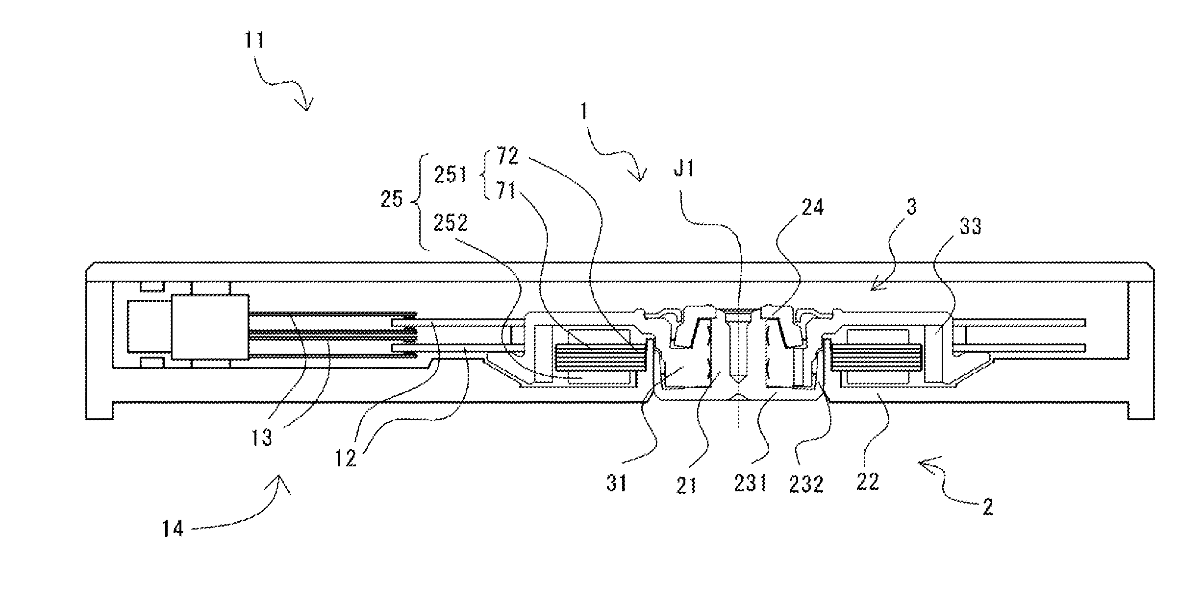
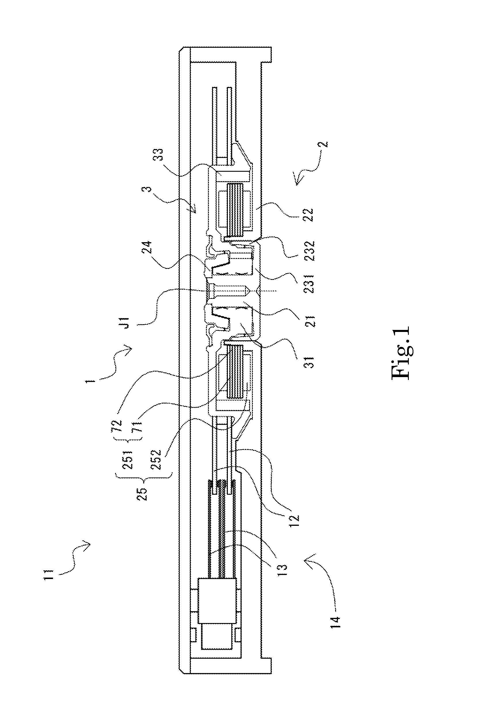
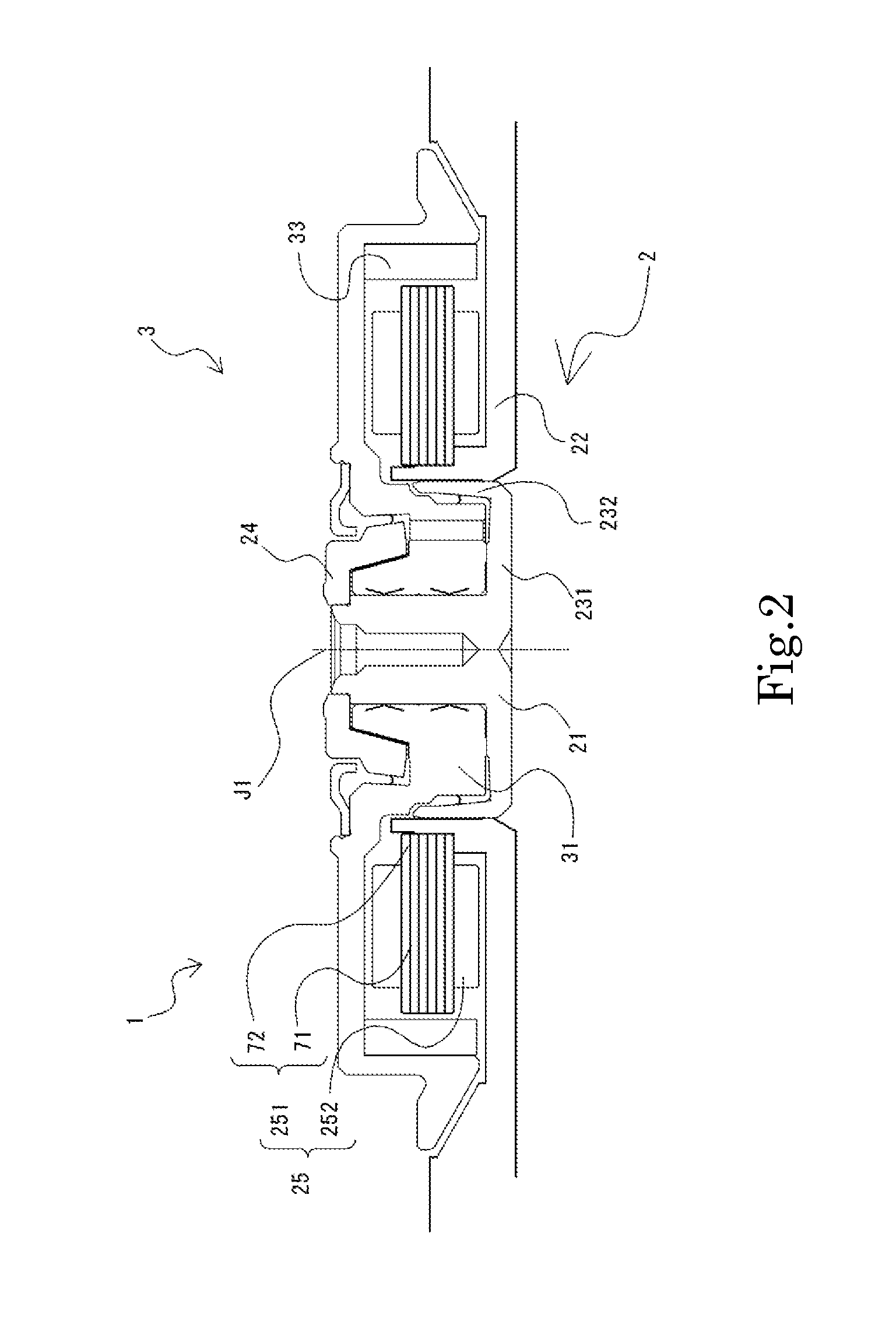
[0017]Hereinafter, exemplary preferred embodiments of the present invention will be described with reference to the accompanying drawings. In the following description, a direction that is parallel or substantially parallel with a central axis of a spindle motor will be referred to as an “axial direction”, a direction that is orthogonal or substantially orthogonal to the central axis of the spindle motor will be referred to as a “radial direction”, and a direction that is along or substantially along an arc about the central axis of the spindle motor will be referred to as a “circumferential direction”. In addition, in this specification, the axial direction is an up-down direction and a stator unit side with respect to a base portion is above in describing shapes and positional relationships of respective portions. However, the definition of the up-down direction does not limit the directions of the spindle motor according to various preferred embodiments of the present invention w...


PUM

PropertyMeasurementUnit
cylindrical shapeaaaaaaaaaa
radial dynamic pressureaaaaaaaaaa
distanceaaaaaaaaaa

Abstract

A spindle motor includes a stationary portion with a shaft, a circular plate portion, a wall portion, and a plate portion. The plate portion has a flat plate portion and an annular convex portion. The sleeve includes an annular portion, an outer side cylindrical portion, and an inner side cylindrical portion. The inner side cylindrical portion and an upper radial dynamic pressure groove array are superimposed in a radial direction. The upper radial dynamic pressure groove array includes a plurality of upper spiral grooves that is inclined in one direction with respect to an axial direction and a plurality of lower spiral grooves that is inclined in another direction opposite to the one direction. A lower end of the upper spiral grooves is positioned farther on an upper side than an upper surface of the annular portion.

Description

BACKGROUND OF THE INVENTION[0001]1. Field of the Invention[0002]The present invention relates to a spindle motor, and more specifically to a disk drive apparatus including a spindle motor.[0003]2. Description of the Related Art[0004]When a motor is to be made thin for a thin hard disk drive apparatus, the oil accommodating volume within the motor also decreases. The maximum possible oil buffer is required in order to accommodate as much oil as possible in a bearing. In addition, the center of gravity is biased to an upper side where a disk is arranged, and thus dynamic pressure that is generated in a radial dynamic pressure bearing portion on the upper side has to be increased.SUMMARY OF THE INVENTION[0005]In order to increase the dynamic pressure, the length of the radial dynamic pressure bearing portion has to be ensured. The inventors of the present application discovered that the radial dynamic pressure bearing portion and an oil buffer portion have to be superimposed in a radia...

Claims


Application Information

Patent Timeline
Patent Type & Authority Applications(United States)
IPC IPC(8): H02K7/08G11B19/20
CPCG11B19/2036H02K7/085F16C17/026F16C17/107F16C33/107G11B19/20G11B19/2009
Inventor YAWATA, ATSUSHIUCHIBORI, HIROTOSHIAKIYAMA, TOSHIHIRO
Owner NIPPON DENSAN CORP
Why Eureka
Try Eureka