Pumping system control

a technology of pumping system and control panel, which is applied in the direction of lighting and heating apparatus, heating types, instruments, etc., can solve the problems of increasing system costs, providing a further source of failure, and not ensuring an optimal energy efficiency of the system

Inactive Publication Date: 2015-03-26
ABB OY
View PDF5 Cites 3 Cited by
  • Summary
  • Abstract
  • Description
  • Claims
  • Application Information

AI Technical Summary

Benefits of technology

[0007]A method of controlling a pump system is disclosed having a pump device and at least two branches, wherein each of the branches has a flow control element, and a pump device control is provided in connection with the pump device, the method comprising: measuring a total flow rate through the pump device before a pump pressure or rotational speed change; changing at least one of: the pump pressure by a predetermined pressure step or the pump rotational speed by a predetermined rotational speed step; measuring a total flow rate through the pump device after the pump pressure or rotational speed change; and determining a need for a further pump pressure or rotational speed change step based on the total flow rate measurements carried out before and after the pump pressure or rotational speed change.
[0008]A control arrangement for a pump system is disclosed having a pump device and at least two branches, wherein each branch has a flow control element, the control arrangement comprising: means for measuring a total flow rate through a pump device, the means for measuring the total flow rate being configured to measure the total flow rate before a pump pressure or rotational speed change and after a pump pressure or rotational speed change; and pump device control means, configured to change, by a predetermined step, at least one of pump pressure or pump rotational speed, the pump device control means being configured to determine a need for a further pump pressure or rotational speed change step based on said total flow rate measurements before and after a pump pressure or rotational speed change.

Problems solved by technology

However, the rotational speed control alone does not ensure an optimal energy efficiency of the system, as the energy efficiency of the pump or an electric motor is not equal to the energy efficiency of the whole system operation.
This involves additional instrumentation and wiring, increasing the system costs and providing a further source of failure, and in many cases, as in connection with a thermostat-controlled radiator based heating system for example, this information is not available in the first place.
In this method, the pump pressure is above the minimal specified pump pressure and, thus, hydraulic losses are not completely minimized, whereby no minimum energy consumption is reached.

Method used


Image

  • Pumping system control
  • Pumping system control
  • Pumping system control

Examples


Embodiment Construction

[0018]A new method and a new arrangement are disclosed for controlling pump systems.

[0019]Exemplary embodiments are based on an idea of utilising known and / or determined pump characteristics and easily determined pressure and / or rotational speed of the pump and flow rate information to find and control a pump pressure setting that can optimize the energy efficiency of the system.

[0020]An exemplary advantage of a method and arrangement disclosed herein can be that the efficiency of pumping systems having two or more branches, each having an independently adjustable control element, can be significantly improved with no need for information about valve settings or angles. Thus, additional instrumentation and wiring can be avoided.

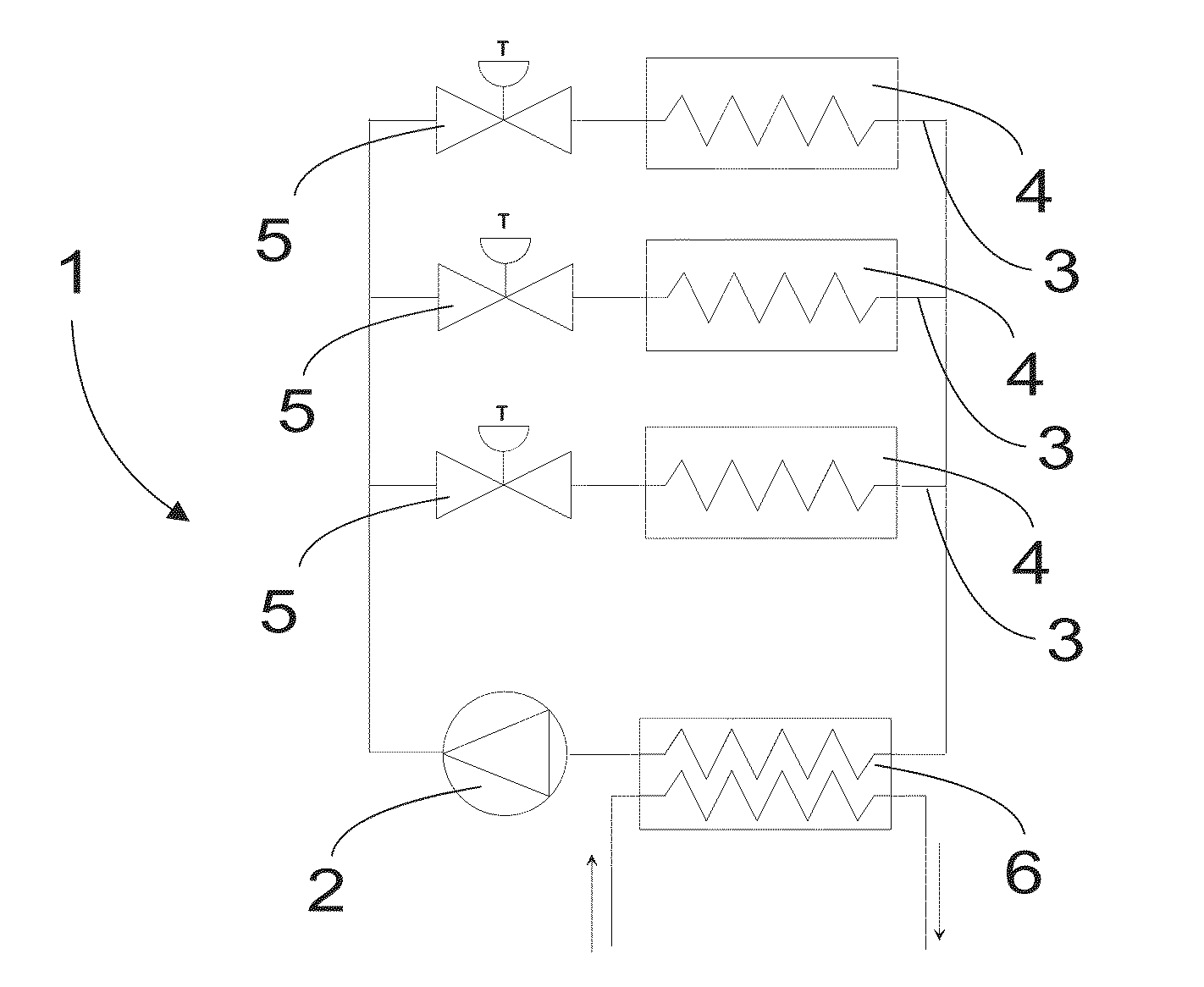
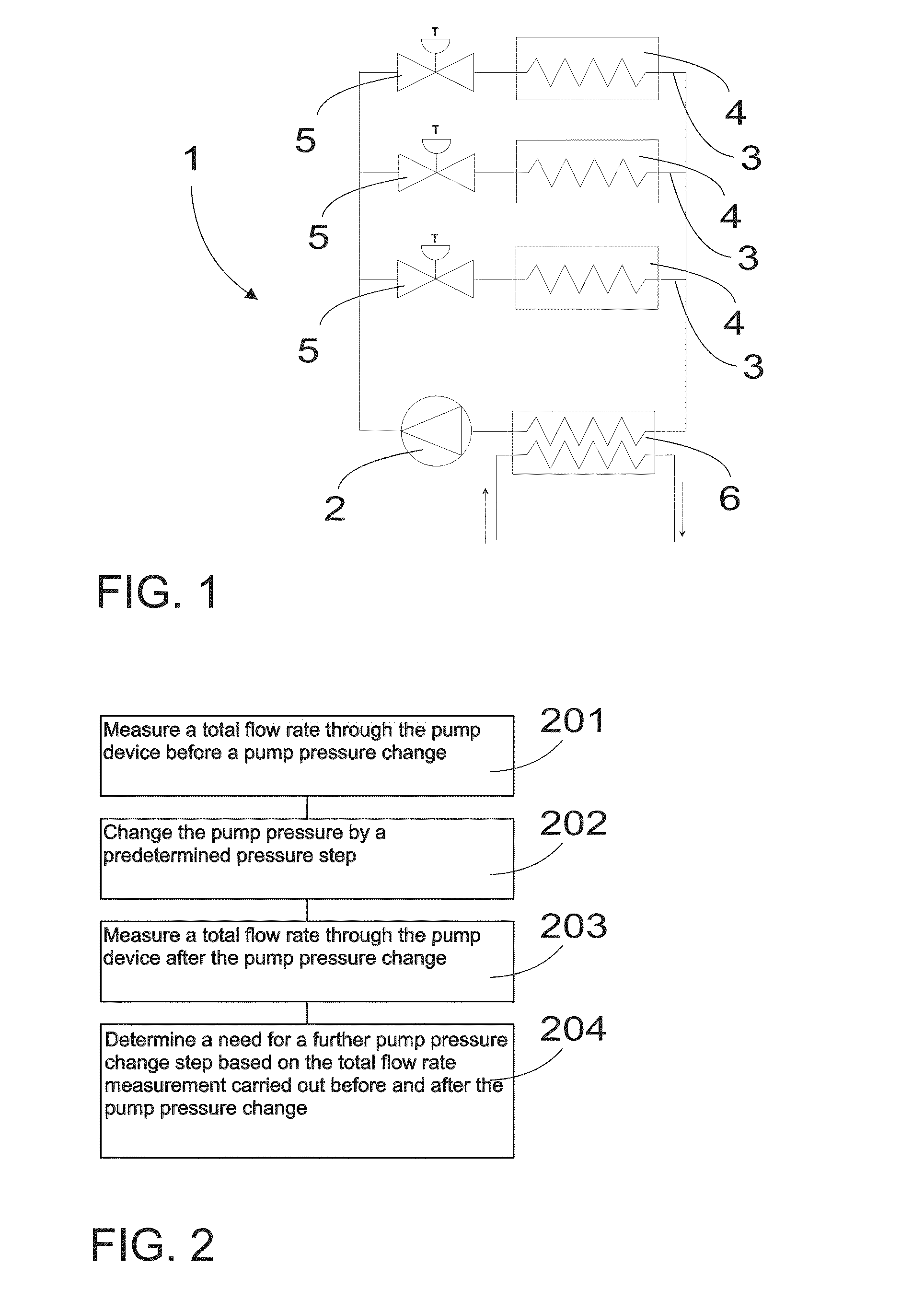
[0021]FIG. 1 schematically illustrates an exemplary pump system. The pump system includes a pump device 2 and at least two branches 3. In the exemplary embodiment of FIG. 1, the pump system 1 includes three branches 3. Each of the branches may include a flow ...


PUM


Abstract

A method and a control arrangement are disclosed to measure a total flow rate through a pump device before a pump pressure or rotational speed change; and to change at least one of: the pump pressure by a predetermined pressure step or the pump rotational speed by a predetermined rotational speed step. The arrangement can measure a total flow rate through the pump device after the pump pressure or rotational speed change; and determine a need for a further pump pressure or rotational speed change step based on total flow rate measurements carried out before and after the pump pressure change.

Description

RELATED APPLICATION[0001]This application claims priority under 35 U.S.C. §119 to European Patent Application No. 13186152.8 filed in Europe on Sep. 26, 2013, the entire content of which is hereby incorporated by reference in its entirety.FIELD[0002]The present disclosure relates to pump system control, and to a control method and arrangement.BACKGROUND INFORMATION[0003]Pumping systems are used in household, industrial and municipal applications. Increased energy consciousness has brought to attention the amount of energy saving potential related to these systems. Variable-speed drives allowing rotational speed control of the pump have been introduced to address the energy efficiency of the pumping system. However, the rotational speed control alone does not ensure an optimal energy efficiency of the system, as the energy efficiency of the pump or an electric motor is not equal to the energy efficiency of the whole system operation.[0004]A pumping system can have the best preconditi...

Claims


Application Information

Patent Timeline
Patent Type & Authority Applications(United States)
IPC IPC(8): G05D7/06
CPCG05D7/0688F24D19/1012Y02B30/70
Inventor TAMMINEN, JUSSIAHONEN, TEROAHOLA, JERO
Owner ABB OY
Why Eureka
Try Eureka