Plasma processing apparatus and plasma processing method

Active Publication Date: 2015-03-26
TOKYO ELECTRON LTD
View PDF6 Cites 17 Cited by
  • Summary
  • Abstract
  • Description
  • Claims
  • Application Information

AI Technical Summary

Benefits of technology

[0008]According to various aspects and exemplary embodiments of the present disclosure, a plasma processing appa

Problems solved by technology

However, in the conventional technology, heat cannot be uniformly transferred to the entire surface of the dielectric even

Method used


Image

  • Plasma processing apparatus and plasma processing method
  • Plasma processing apparatus and plasma processing method
  • Plasma processing apparatus and plasma processing method

Examples


Embodiment Construction

[0021]Hereinafter, exemplary embodiments will be described in detail with reference to drawings. In each drawing, the same or equivalent portions will be denoted by the same reference numerals.

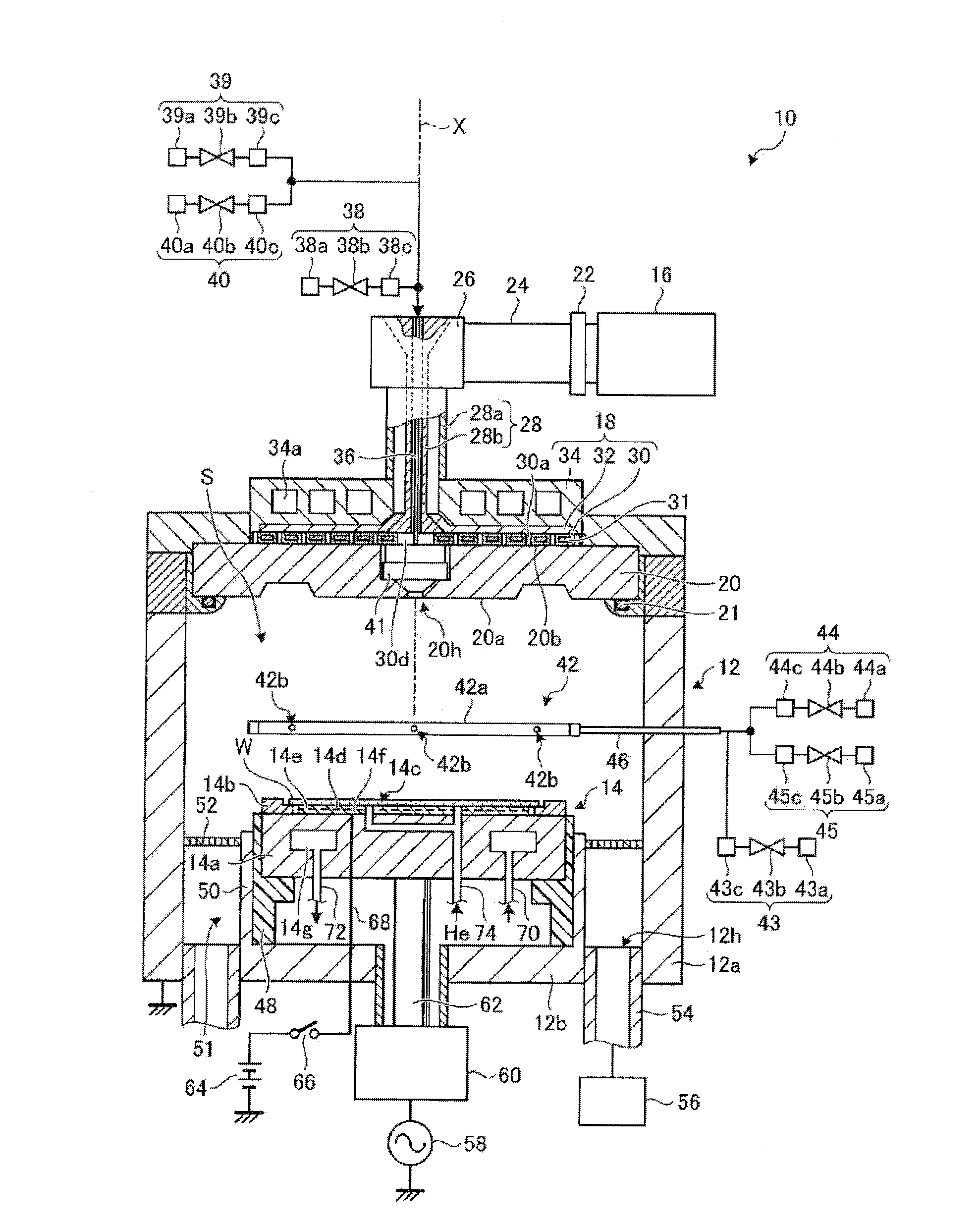
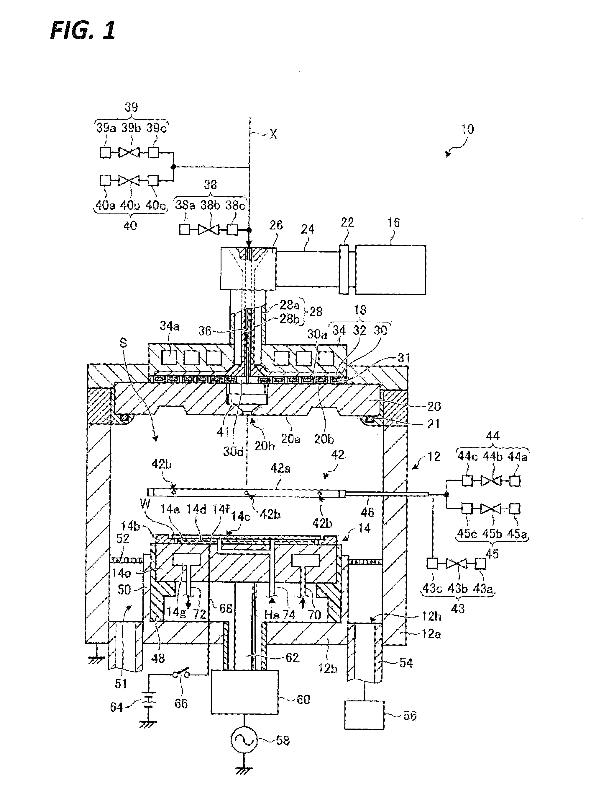
[0022]FIG. 1 is a view schematically illustrating a plasma processing apparatus according to an exemplary embodiment. A plasma processing apparatus 10 illustrated in FIG. 1 includes a processing container 12, a stage 14, a microwave generator 16, an antenna 18, and a dielectric window 20.

[0023]The processing container 12 defines a processing space S for performing a plasma processing. The processing container 12 includes a side wall 12a, and a bottom portion 12b. The side wall 12a is formed in a substantially tubular shape. Hereinafter, an X axis along which the tubular shape extends is virtually set at the center of the tubular shape of the side wall 12a, and the extension direction of the X axis is referred to as an X axis direction. The bottom portion 12b is provided at the bottom side of t...


PUM

PropertyMeasurementUnit
aaaaaaaaaa

Abstract

A plasma processing apparatus includes: a processing container which defines a processing space; a microwave generator; a dielectric having an opposing surface which faces the processing space; a slot plate formed with a plurality of slots; and a heating member provided within the slot plate. The slot plate is provided on a surface of the dielectric at an opposite side to the opposing surface to radiate microwaves for plasma excitation to the processing space through the dielectric based on the microwaves generated by the microwave generator.

Description

TECHNICAL FIELD[0001]Various aspects and exemplary embodiments of the present disclosure relate to a plasma processing apparatus and a plasma processing method.BACKGROUND ART[0002]In a semiconductor manufacturing process, a plasma processing is widely performed for the purpose of, for example, etching or deposition of a thin film. In order to obtain a semiconductor which has a high performance and high function, it is requested that the plasma processing be uniformly performed on an entire processing target surface of a substrate to be processed.[0003]In a recent plasma processing, a plasma processing apparatus using excitation of a process gas by microwaves has been used. The plasma processing apparatus irradiates microwaves generated by a microwave generator as microwaves for plasma excitation by using a slot plate having a plurality of slots formed therein. The plasma processing apparatus guides the microwaves for plasma excitation, which are irradiated from the slot plate, to a ...

Claims


Application Information

Patent Timeline
IPC IPC(8): H01L21/67H01L21/3065H01L21/263
CPCH01L21/67069H01L21/3065H01L21/2636C23C16/511H05H1/46C23C16/405H01J37/32192H01J37/3222H01L21/324H05H1/463
Inventor MATSUMOTO, NAOKI
Owner TOKYO ELECTRON LTD
Why Eureka
Try Eureka