Suspension system

a suspension system and suspension technology, applied in the field of suspension systems, can solve the problems of reducing maneuverability and stability, reducing the maneuverability (the driving experience) of the driver, and raising the drawback of not only the shock absorber, but also the air suspension, hydraulic stabilizers, etc., to achieve the effect of improving maneuverability and stability

Active Publication Date: 2015-03-26
HITACHI ASTEMO LTD
View PDF12 Cites 37 Cited by
  • Summary
  • Abstract
  • Description
  • Claims
  • Application Information

AI Technical Summary

Benefits of technology

[0006]The present invention has been contrived in consideration of the above-described drawback in the conventional technique, and an object of the present invention is to provide a suspension system capable of improving the maneuverability and the stability.

Problems solved by technology

Therefore, if the damping force characteristic of the shock absorber is adjusted (controlled) out of consideration of the longitudinal force and the lateral force applied to the wheel, and thus the forces applied to the vehicle body based on these longitudinal force and lateral force, this may leads to excessiveness or insufficiency of the damping force, resulting in, for example, a reduction in maneuverability (a driver's maneuvering feeling) and stability.
This drawback is raised in not only the shock absorber, but also an air suspension, a hydraulic stabilizer, and the like.

Method used


Image

  • Suspension system
  • Suspension system
  • Suspension system

Examples


first embodiment

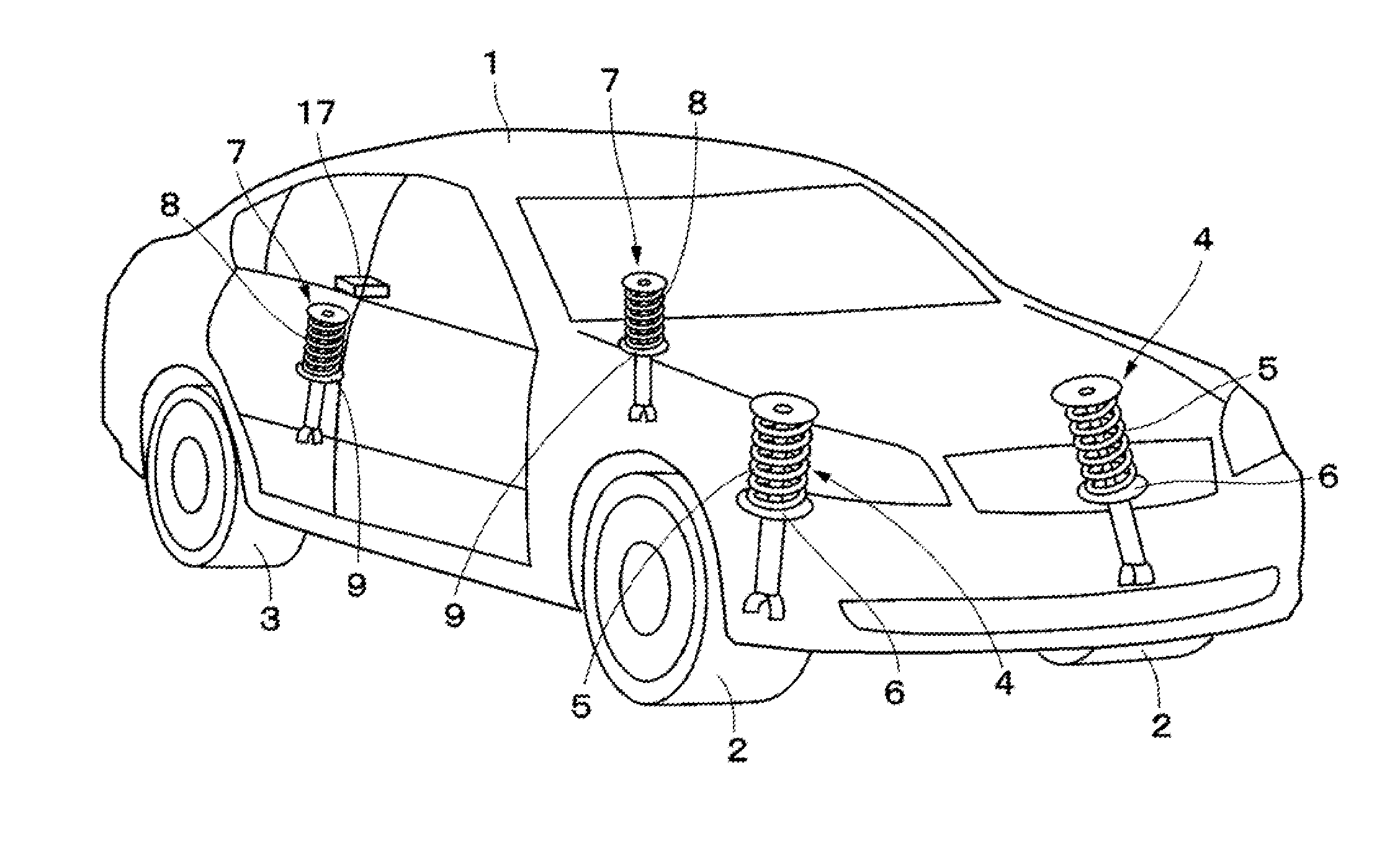
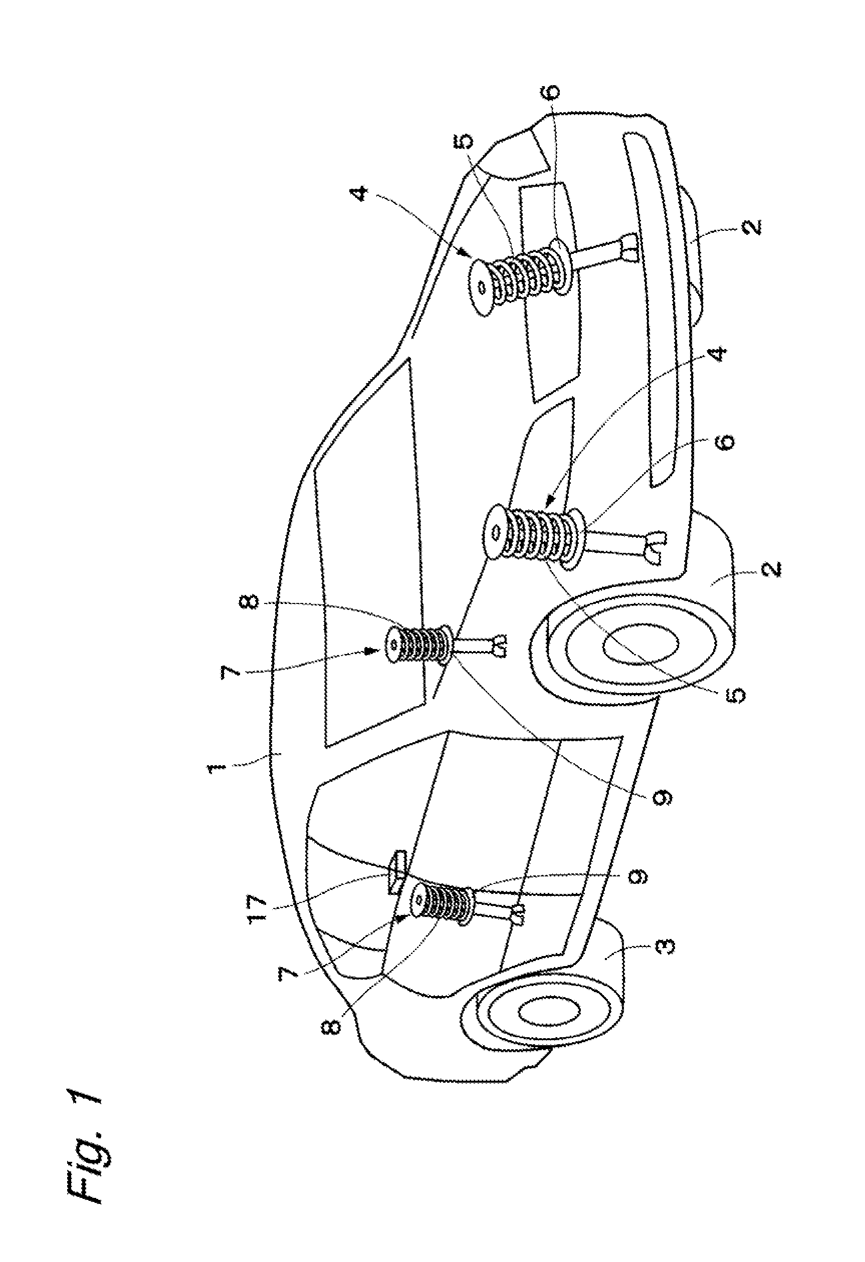
[0020]FIGS. 1 to 4 illustrate the present invention. Referring to FIG. 1, for example, front left and right wheels 2 and rear left and right wheels 3 (only one of the rear wheels 3 is illustrated in FIG. 1), i.e., four wheels 2 and 3 in total are disposed below a vehicle body 1, which constitutes a main structure of a vehicle.

[0021]Front wheel side suspensions 4 and 4 (hereinafter referred to as front wheel suspensions 4) are disposed between the front left and right wheels 2 and the vehicle body 1. The left and right front wheel suspensions 4 include left and right suspension springs 5 (hereinafter referred to as springs 5), left and right damping force adjustable shock absorbers (hereinafter referred to as shock absorbers 6) disposed between the front left and right wheels 2 and the vehicle body 1 in parallel with the respective springs 5, links 10 illustrated in FIGS. 3 and 4, and the like. These damping force adjustable shock absorbers 6 correspond to a force generation mechanis...

second embodiment

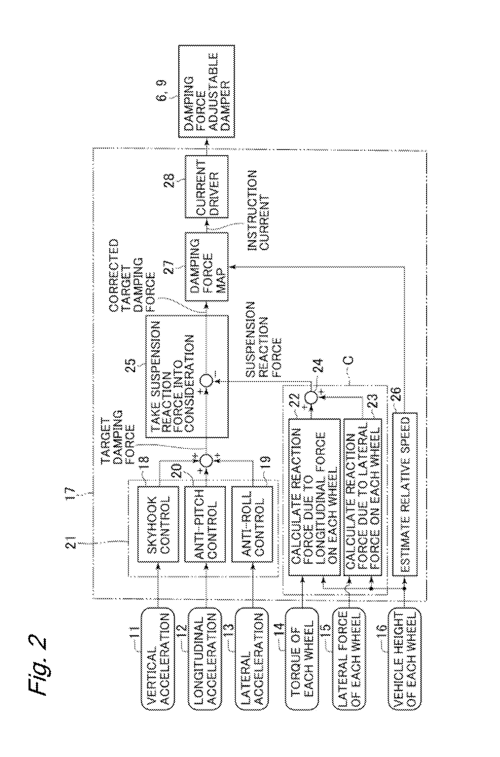
[0091] configured in this manner, the controller 33 controls each of the shock absorbers 6 and 9 (adjust the damping force), for example, as illustrated in FIG. 6.

[0092]For example, suppose that the electronic stability control system (ESC), which applies a braking force to the predetermined wheel 2 or 3 according to the posture of the vehicle, or the traffic lane departure prevention system, which applies a braking force to the predetermined wheel 2 or 3 according to the relationship between the vehicle and the traffic lane, is actuated while the vehicle is running. When a braking force is applied to, for example, only the front right wheel 2 (and the rear right wheel 3) due to this actuation, the difference between the torques on the left side and the right side, which has a positive value, is output from the subtraction unit 37. Then, the difference between the longitudinal forces on the left side and the right side is output from the longitudinal force calculation unit 38 as a p...


PUM


Abstract

The present invention is directed to providing a suspension system capable of improving maneuverability and stability. A controller, which controls each of shock absorbers, includes a main control calculation unit, a longitudinal force reaction force calculation unit, a lateral force reaction force calculation unit, an addition unit, and a suspension reaction force consideration unit. The controller subtracts an output from a vertical force calculation unit including the longitudinal force reaction force calculation unit, the lateral force reaction force calculation unit, and the addition unit from an output from the main control calculation unit by the suspension reaction force consideration unit, thereby succeeding in calculating a vertical force applied between a vehicle body and each wheel as a value in consistency with an actual behavior of a vehicle.

Description

BACKGROUND OF THE INVENTION[0001]The present invention relates to a suspension system mounted on a vehicle such as an automobile, and preferably used for absorbing a vibration of the vehicle[0002]One generally known type of a suspension system mounted on a vehicle such as an automobile is a suspension system configured to include a shock absorber (a damping force adjustable shock absorber) capable of adjusting a damping force between a vehicle body and each wheel, and adjust (control) a damping force characteristic of the shock absorber with use of a control unit (a controller) (for example, refer to Japanese Patent Application Public Disclosure No. 2011-173503).[0003]The suspension system discussed in Japanese Patent Application Public Disclosure No. 2011-173503 is configured to perform anti-dive control of changing the damping force characteristic to the hard side when the vehicle is braked, and change at least an extension-side damping force characteristic to the soft side if a w...

Claims


Application Information

Patent Timeline
Patent Type & Authority Applications(United States)
IPC IPC(8): B60G17/015
CPCB60G17/015B60G17/016B60G17/08B60G2202/24B60G2202/25B60G2400/102B60G2400/104B60G2400/106B60G2400/252B60G2400/50B60G2400/64B60G2500/104B60G2800/012B60G2800/014B60G2800/162
Inventor HIRAO, RYUSUKE
Owner HITACHI ASTEMO LTD
Why Eureka
Try Eureka