
Lighting control console and lighting control system

a control console and lighting technology, applied in the field of lighting control consoles and lighting control systems, can solve the problems of difficulty for users to recognize differences in the depth direction of the stage, and achieve the effect of improving the workability of operation

Inactive Publication Date: 2015-04-02
PANASONIC INTELLECTUAL PROPERTY MANAGEMENT CO LTD
View PDF24 Cites 20 Cited by
  • Summary
  • Abstract
  • Description
  • Claims
  • Application Information

AI Technical Summary

Benefits of technology

The invention aims to improve the usability of selecting lighting instruments using a lighting control console and system. Compared to previous examples that use touch panels, the invention makes the operation easier and more efficient.

Problems solved by technology

It is therefore difficult for a user to recognize a difference in a depth direction of the stage by the two dimensional image of the stage displayed on the display (i.e., by the image of the stage taken by the camera).

Method used


Image

  • Lighting control console and lighting control system
  • Lighting control console and lighting control system
  • Lighting control console and lighting control system

Examples


Embodiment Construction

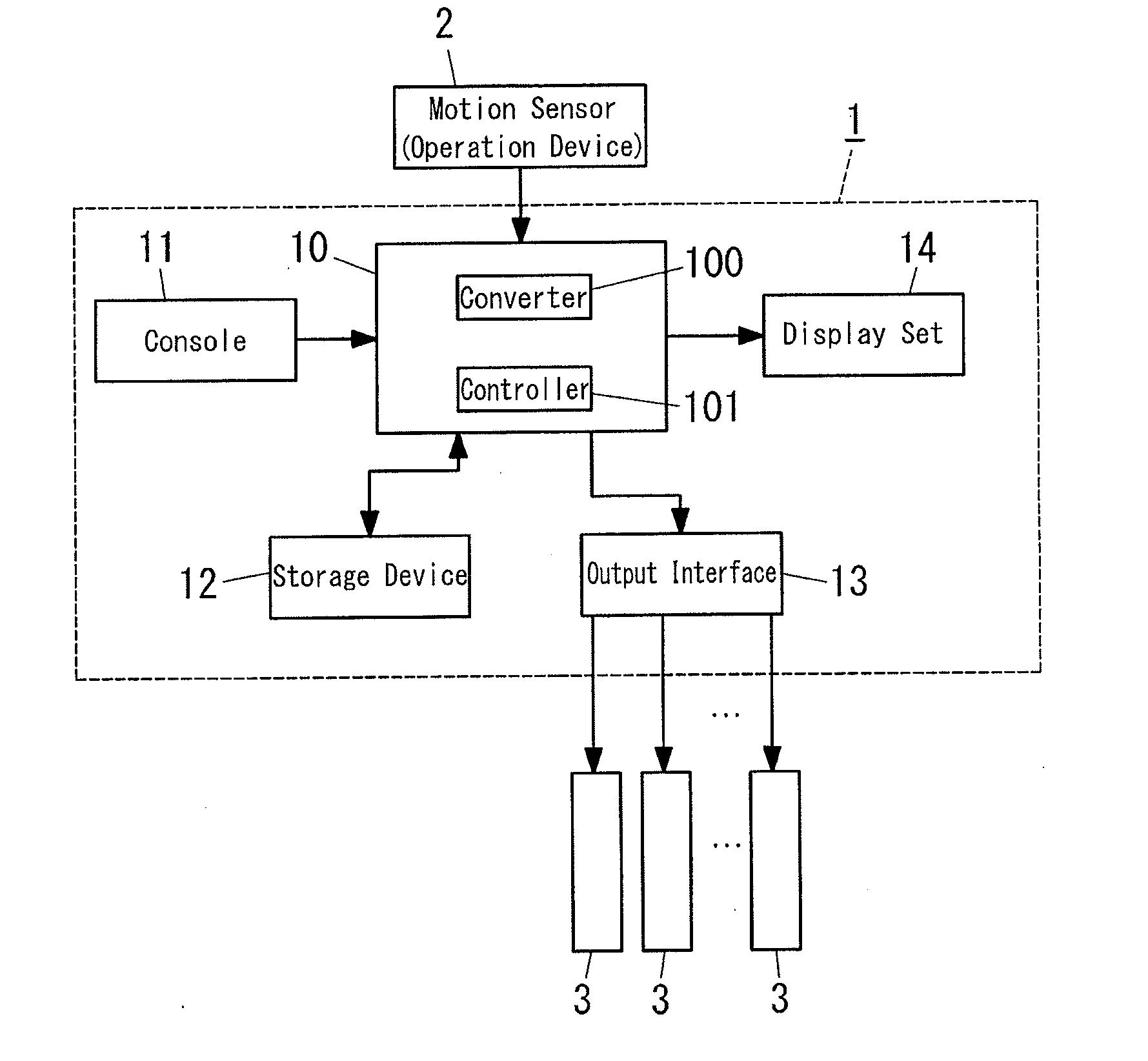
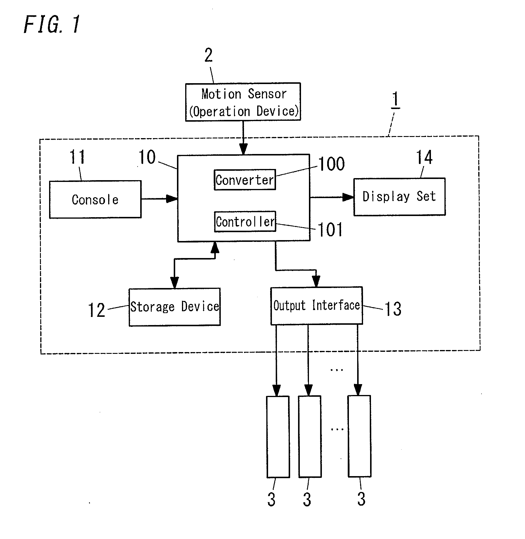
[0015]A lighting control console and a lighting control system according to the present embodiment will be described in detail with reference to attached figures. The lighting control system of the embodiment is adapted to control stage lighting of a lighting space 4 (such as a theater stage shown in FIG. 4). The lighting space 4 is defined, for example, as a space enclosed by a floor face 40, a back face 41, a left face 42, a right face 43, a top face 44, and a front face (which is a virtual face; not shown). In the example of FIG. 4, two or more battens 45 (two of them are shown in FIG. 4) are arranged in an top side of the stage (lighting space) 4 in parallel with each other, and lighting instruments 3 are hung from the battens 45.

[0016]The lighting instrument 3 according to the embodiment is, what is called, a moving spotlight, and is configured so that at least one of a pan angle (horizontal angle about the vertical axis), a tilt angle (vertical angle about a horizontal axis), ...


PUM


Abstract

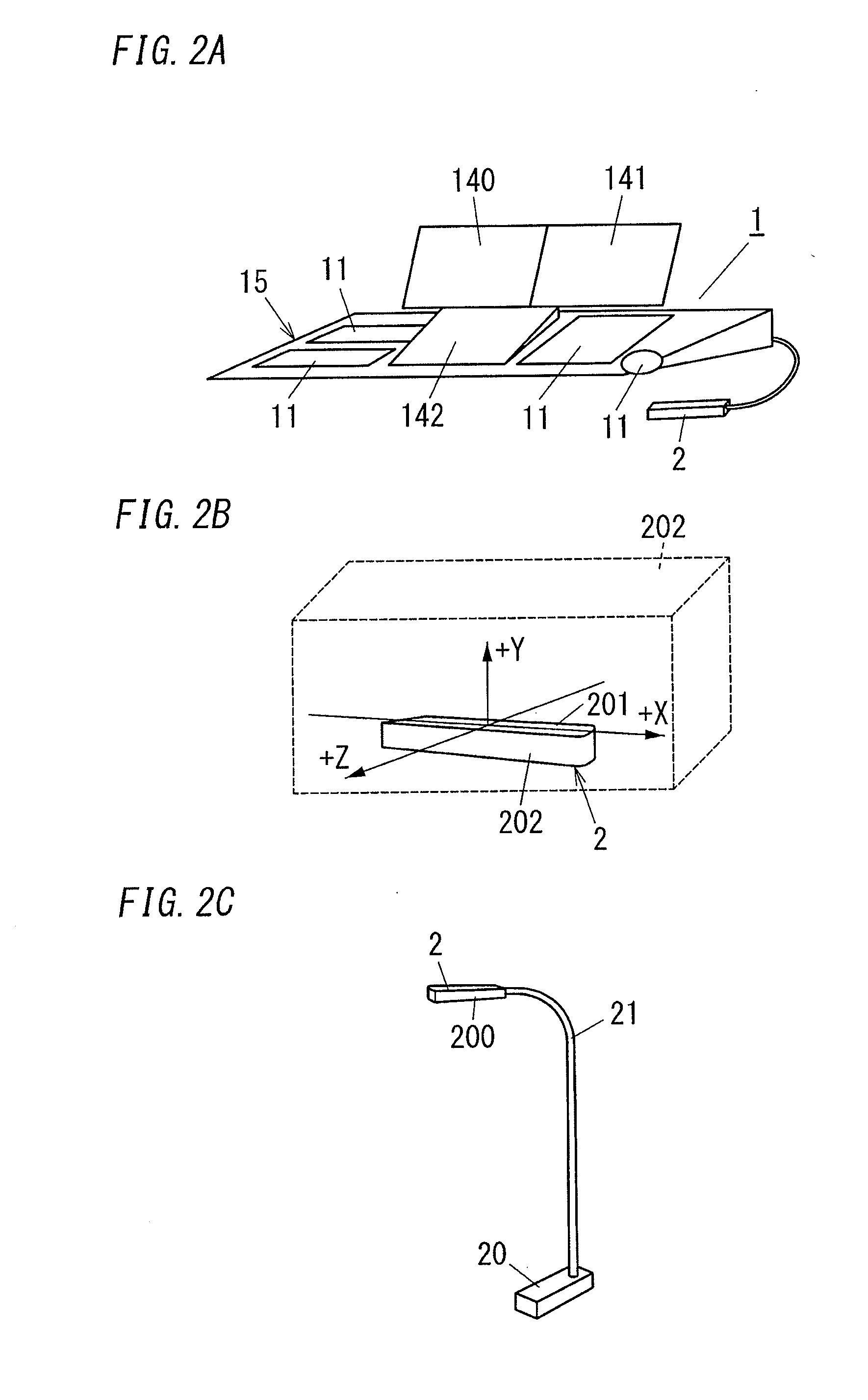
The lighting control console includes a display, an operation device and a controller. The display displays a lighting spatial image corresponding to the lighting space, and displays, in the lighting spatial image, virtual instruments corresponding to the respective lighting instruments so that positions of the virtual instruments in the lighting spatial image correspond to respective positions of the lighting instruments in the lighting space. The operation device has a three dimensional detection space associated with the lighting spatial image and / or the lighting space. The operation device detects a position of an operation object in the detection space and specifies a position in the lighting spatial image based on the detected position in the detection space. The controller identifies, when one of the virtual instruments in the lighting spatial image is specified by the operation object through the operation device, a lighting instrument associated with the specified virtual instrument.

Description

CROSS-REFERENCE TO RELATED APPLICATIONS[0001]The application is based upon and claims the benefit of priority of Japanese Patent Application No. 2013-204689, filed on Sep. 30, 2013, the entire contents of which are incorporated herein by reference.TECHNICAL FIELD[0002]The disclosure relates generally to lighting control consoles and lighting control systems and, more particularly, to a lighting control console and a lighting control system for controlling stage lighting of a theater stage, a broadcasting studio, and the like.BACKGROUND ART[0003]JP2012-69423A (hereinafter, referred to as “Document 1”) discloses a lighting control device as a conventional example. This conventional example is configured to take by a camera an image of a stage in which a number of lighting instruments are installed, and to display the image of the stage on a monitor-display with a touch panel. This conventional example enables a user to select a lighting instrument by touching a symbol of the lighting ...

Claims


Application Information

Patent Timeline
IPC IPC(8): H05B37/02
CPCH05B37/0227G06F3/0346H05B47/125H05B47/155Y02B20/40
Inventor OHTA, KENJIIWATA, NOBUO
Owner PANASONIC INTELLECTUAL PROPERTY MANAGEMENT CO LTD
Learn More