Solid state energy storage and management system

a technology of which is applied in the direction of motor/generator/converter stopper, dynamo-electric converter control, capacitor propulsion, etc., can solve the problems of high initial cost of installation, insufficient traditional energy storage and management system, and operators' inability to choos

Active Publication Date: 2015-04-02
VELOCITY MAGNETICS
View PDF60 Cites 25 Cited by
  • Summary
  • Abstract
  • Description
  • Claims
  • Application Information

AI Technical Summary

Problems solved by technology

Traditional systems for energy storage and management, particularly in the amusement ride industry are not adequate.
This installation has a very high initial cost, and may require the operator to pull power directly from the power grid.
Some operators do not have this option due to the size of their electrical infrastructure or where the service would have to be physically installed on their property.
Operators who provide moveable or transient rides, such as traveling carnivals, cannot provide certain types of amusement rides because of inadequate power supply.
Nevertheless, a flywheel generator and out-building to house and support the generator may be expensive, heavy, and often noisy.
Further, the flywheel generator may be unable to store electrical energy converted from kinetic energy efficiently due to mechanical losses or the like.
Amusement park operators typically do not like the idea of pulling the required large amount of energy from the electrical grid at one time and some are not able to install large three phase electrical services at particular geographical locations on the properties.
Operators typically do not want the added expense or maintenance of a flywheel generator nor do they want to build a secondary out building to house the generator.

Method used


Image

  • Solid state energy storage and management system
  • Solid state energy storage and management system
  • Solid state energy storage and management system

Examples


Embodiment Construction

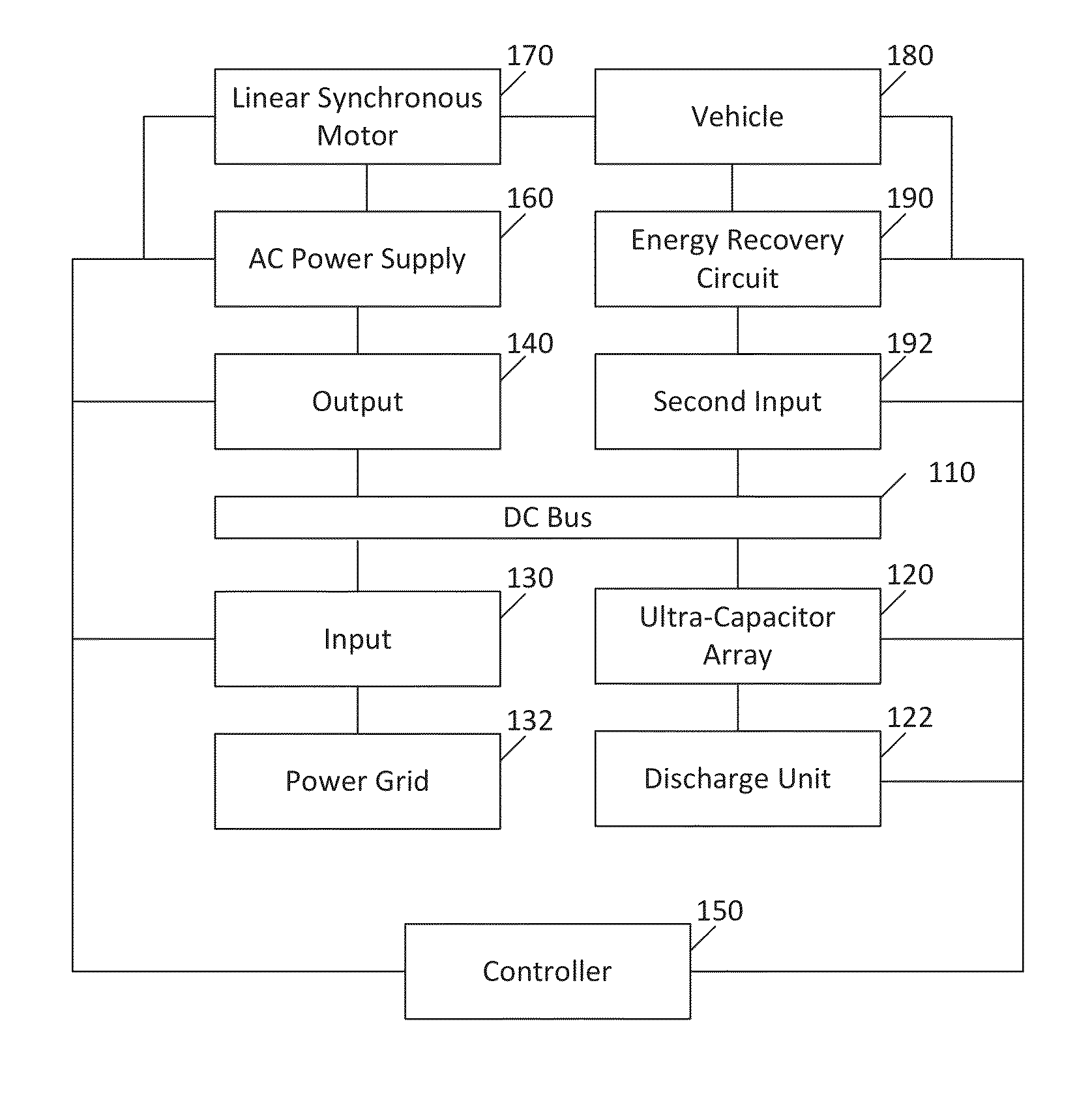
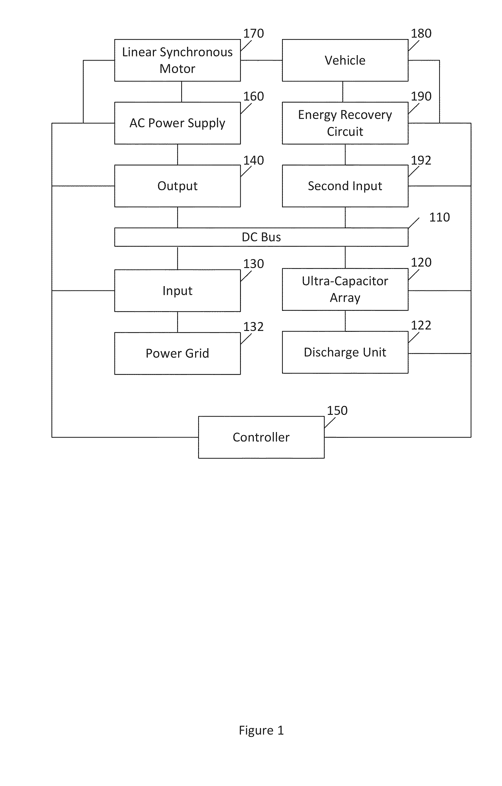
[0018]Embodiments of the present invention solve many of the problems and / or overcome many of the drawbacks and disadvantages of the prior art by providing systems and methods for energy storage and management. Systems and methods are described for using various tools and procedures for energy storage and management. A system of certain embodiments of the present invention may be referred to herein as an Solid State Energy Storage and Management System. In certain embodiments, the tools and procedures may be used in conjunction with launch devices. The tools and procedures may couple the system with a braking system that can harvest some of the kinetic energy and store the harvested energy for a future discharge or launch. In certain embodiments, the system may be about a 0.5-5 MW system.

[0019]The examples described herein relate to amusement park launch devices for illustrative purposes only. The systems and methods described herein may be used for many different industries and pur...


PUM


Abstract

Systems and methods for energy storage and management may be useful for a variety of applications, including launch devices. A system can include a direct current (DC) bus configured to operate within a predetermined range of voltages. The system can also include an array comprising a plurality of ultra-capacitors connected to the DC bus and configured to supply the DC bus with energy. The system can further include an input configured to receive energy from a power grid, wherein the power grid is configured to supply fewer than 250 amps of power. The system can additionally include an output configured to supply more than 250 amps of power. The system can also include a controller configured to control charging and discharging of the array of ultra-capacitors and configured to control the DC bus to remain within the predetermined range of voltages.

Description

CROSS REFERENCE TO RELATED APPLICATIONS[0001]This application is related to and claims the benefit and priority of U.S. Provisional Application No. 61 / 885,968, filed Oct. 2, 2013, the entirety of which is hereby incorporated herein by reference.BACKGROUND[0002]1. Field[0003]Certain embodiments of the present invention relate to systems and methods for energy storage and management. For example, certain embodiments relate to systems and methods for solid state energy storage and management.[0004]2. Description of the Related Art[0005]Traditional systems for energy storage and management, particularly in the amusement ride industry are not adequate. Typically, the park operator has to install a large, for example 1000+ amperage, service along with a very large transformer and large conductors, such as thick wires or cables. This installation has a very high initial cost, and may require the operator to pull power directly from the power grid. Some operators do not have this option due...

Claims


Application Information

Patent Timeline
Patent Type & Authority Applications(United States)
IPC IPC(8): H02P6/00H02P3/14
CPCH02P3/14H02P6/006B60L15/005H02J7/345A63G7/00B60L13/03H02P31/00B60L53/22B60L50/40B60L7/28Y02T10/64Y02E60/16Y02T10/70Y02T10/7072Y02T90/14Y02T90/12
Inventor MARZANO, DOMENIC P.
Owner VELOCITY MAGNETICS
Why Eureka
Try Eureka