
Vortex mixing apparatus and method of use thereof

a technology of mixing apparatus and vortex, which is applied in the direction of non-electric variable control, process and machine control, instruments, etc., can solve the problems of reducing yield, reducing efficiency of exothermic reaction at higher flow rate, and insufficient mixing methods

Active Publication Date: 2015-04-02
BEDOUKIAN RES
View PDF2 Cites 4 Cited by
  • Summary
  • Abstract
  • Description
  • Claims
  • Application Information

AI Technical Summary

Benefits of technology

The patent describes a method and reactor that can mix materials effectively on a small scale and remove products from the reaction. This method reduces the buildup of reaction byproducts and partially reacted materials, and it is simple and economical compared to other mixing methods. The reactor remains stationary during operation, which avoids the need for costly and often failure-prone seals. Overall, this method and reactor have improved mixing efficiency and product purity.

Problems solved by technology

However, such methods of mixing may not be sufficient in certain cases of instantaneous reactions in which side products are possible.
The buildup of desired products can react again with starting materials and reduce yields.
The mixing in a tube relies on the flow rate of the material and exothermic reactions may not be cooled efficiently at higher flow rates.
A sufficiently small tube in which mixing can occur via diffusion with good heat transfer solves this problem but limits throughput as well as limits any particulate matter from being introduced or formed during the reaction.
These systems have many benefits but require extensive engineering requirements and / or expensive seals.
These systems also tend to have shearing elements of 100-500 uM size, which can limit the usefulness with solid feeds / formation.
Exothermic reactions can potentially form undesirable side products at certain temperatures and to control this temperature increase, either flow rates need to be lowered or starting materials must be diluted.

Method used


Image

  • Vortex mixing apparatus and method of use thereof
  • Vortex mixing apparatus and method of use thereof
  • Vortex mixing apparatus and method of use thereof

Examples


Embodiment Construction

[0018]Embodiments of the present disclosure now are described more fully hereinafter with reference to the accompanying drawings, in which some, but not all, embodiments of the disclosure are shown. Indeed, the disclosure can be embodied in many different forms and should not be construed as limited to the embodiments set forth herein. Rather, these embodiments are provided so that this disclosure may satisfy applicable legal requirements. Like numbers refer to like elements throughout.

[0019]The terms “comprises” or “comprising” are to be interpreted as specifying the presence of the stated features, integers, steps or components, but not precluding the presence of one or more other features, integers, steps or components or groups thereof.

[0020]Where possible, any terms expressed in the singular form herein are meant to also include the plural form and vice versa, unless explicitly stated otherwise. Also, as used herein, the term “a” and / or “an” shall mean “one or more,” even thoug...


PUM


Abstract

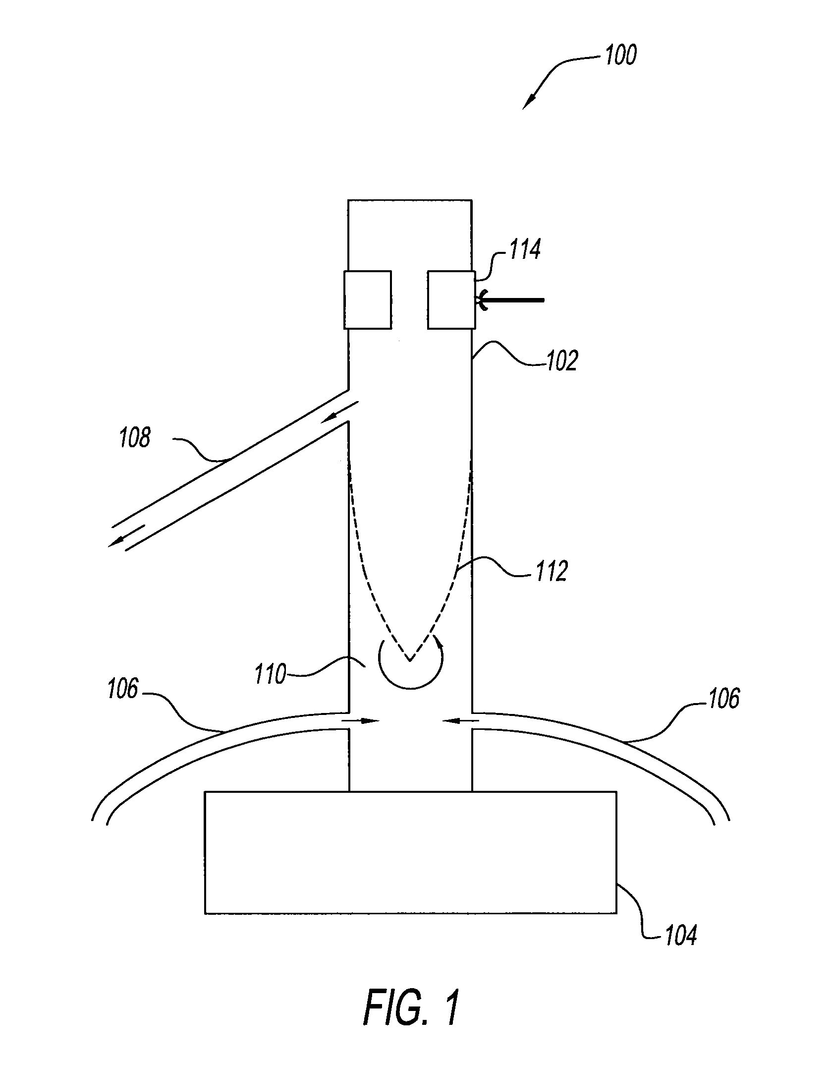
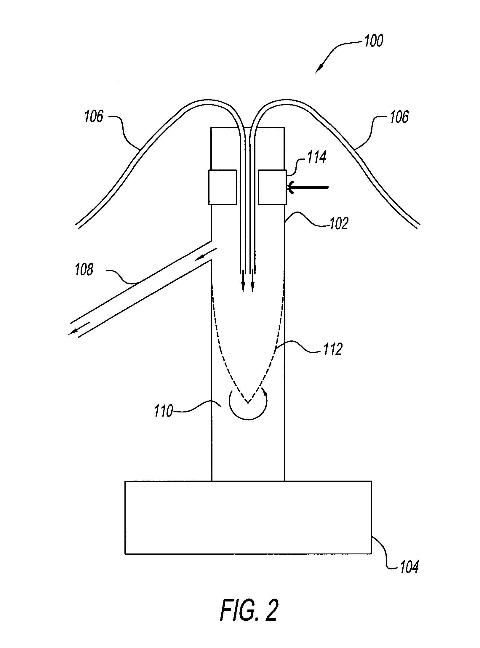
A apparatus comprising: a vessel component comprising a flow-through interior chamber having an interior sidewall and an exterior sidewall; at least two inlets for introducing chemical components into the flow-through interior chamber; at least one outlet for removing product from the flow-through interior chamber; and an off center rotation component which is operatively connected to the vessel component. During operation of the apparatus, the off center rotation component generates vortical movement of at least two chemical components through the flow-through interior chamber of the vessel, and converts at least a portion of the at least two chemical components to at least one reaction product or product mixture. A method of using the apparatus to produce reaction products or product mixtures. The apparatus and method are useful for producing specialty chemicals such as fragrance and flavor compounds, insect pheromones, petrochemicals, pharmaceutical compounds, agrichemical compounds, and the like.

Description

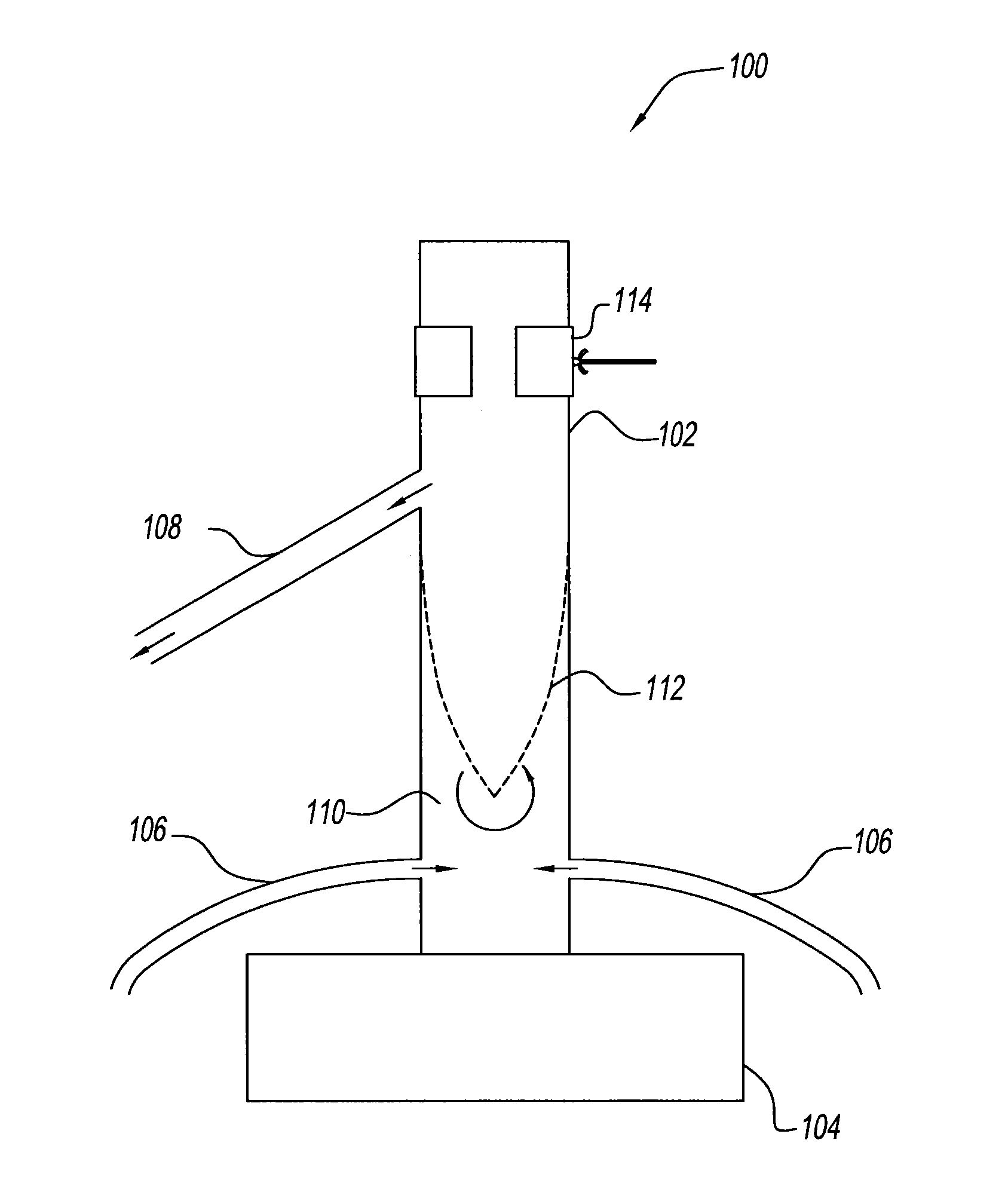
RELATED APPLICATION[0001]This application claims the benefit of U.S. Provisional Application Ser. No. 61 / 884,615, filed on Sep. 30, 2013, which is incorporated herein by reference.BACKGROUND OF THE DISCLOSURE[0002]1. Field of the Disclosure[0003]This disclosure relates to a vortex mixing apparatus and a method of use thereof. In particular, this disclosure involves generating vortical movement of a fluid in a flow vessel by an external oscillatory surface.[0004]2. Description of the Related Art[0005]It is well-known that the reaction rate between two or more chemical constituents is enhanced by bringing the constituents into more intimate contact. Thus various types of mixing, stirring, agitating, and / or centrifuging methods have been used to produce faster and more complete reaction between two or more chemical constituents. However, such methods of mixing may not be sufficient in certain cases of instantaneous reactions in which side products are possible. The buildup of desired p...

Claims


Application Information

Patent Timeline
IPC IPC(8): B01F5/00B01F3/04B01F3/12B01F15/04B01F15/06
CPCB01F5/0057B01F15/0479B01F15/06B01F2215/0036B01F3/04B01F2005/0017B01F2015/062B01F3/12B01J8/222B01J19/2405B01J19/28B01J19/285B01F2215/0431B01F2215/0468B01J2208/00203B01J2208/00212B01J2219/0009B01J2219/00094B01F2025/913B01F31/265B01F31/57B01F35/7542B01F35/92B01F2035/99
Inventor BEDOUKIAN, MATTHEW
Owner BEDOUKIAN RES
Learn More