Optically pumped vertical external-cavity surface-emitting laser device

Active Publication Date: 2015-04-02
KONINKLIJKE PHILIPS ELECTRONICS NV
View PDF5 Cites 15 Cited by
  • Summary
  • Abstract
  • Description
  • Claims
  • Application Information

AI Technical Summary

Benefits of technology

[0005]It is an object of the present invention to provide an optically pumped vertical external-cavity surface-

Problems solved by technology

In standard setups the external cavity is composed of macroscopic optical elements, which are ve

Method used


Image

  • Optically pumped vertical external-cavity surface-emitting laser device
  • Optically pumped vertical external-cavity surface-emitting laser device
  • Optically pumped vertical external-cavity surface-emitting laser device

Examples


Embodiment Construction

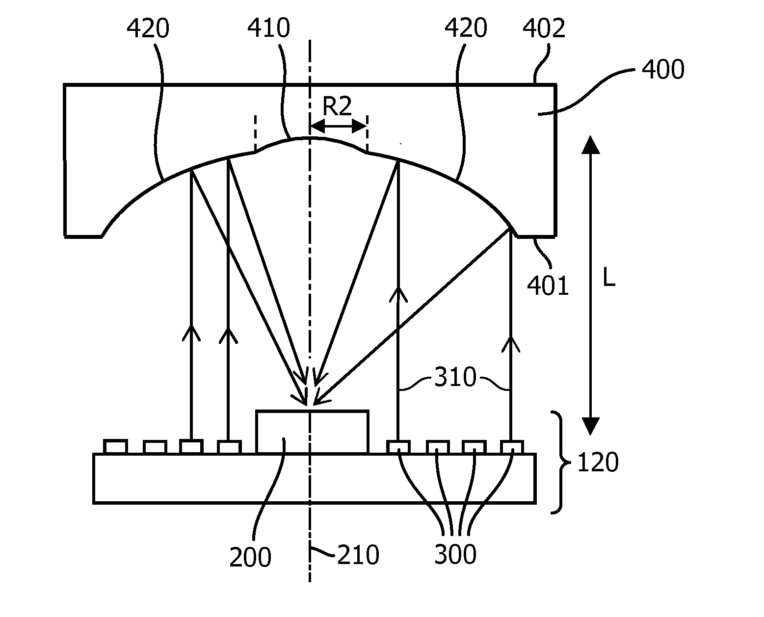
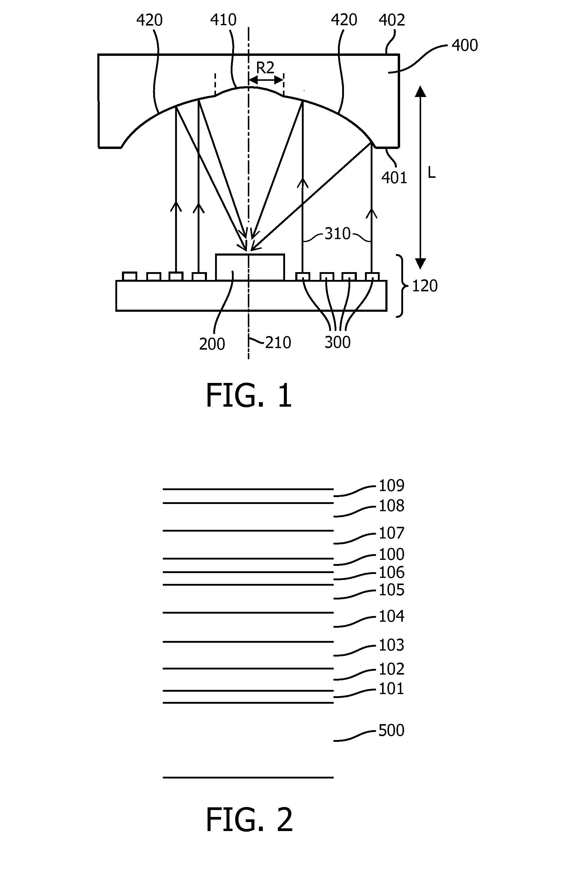
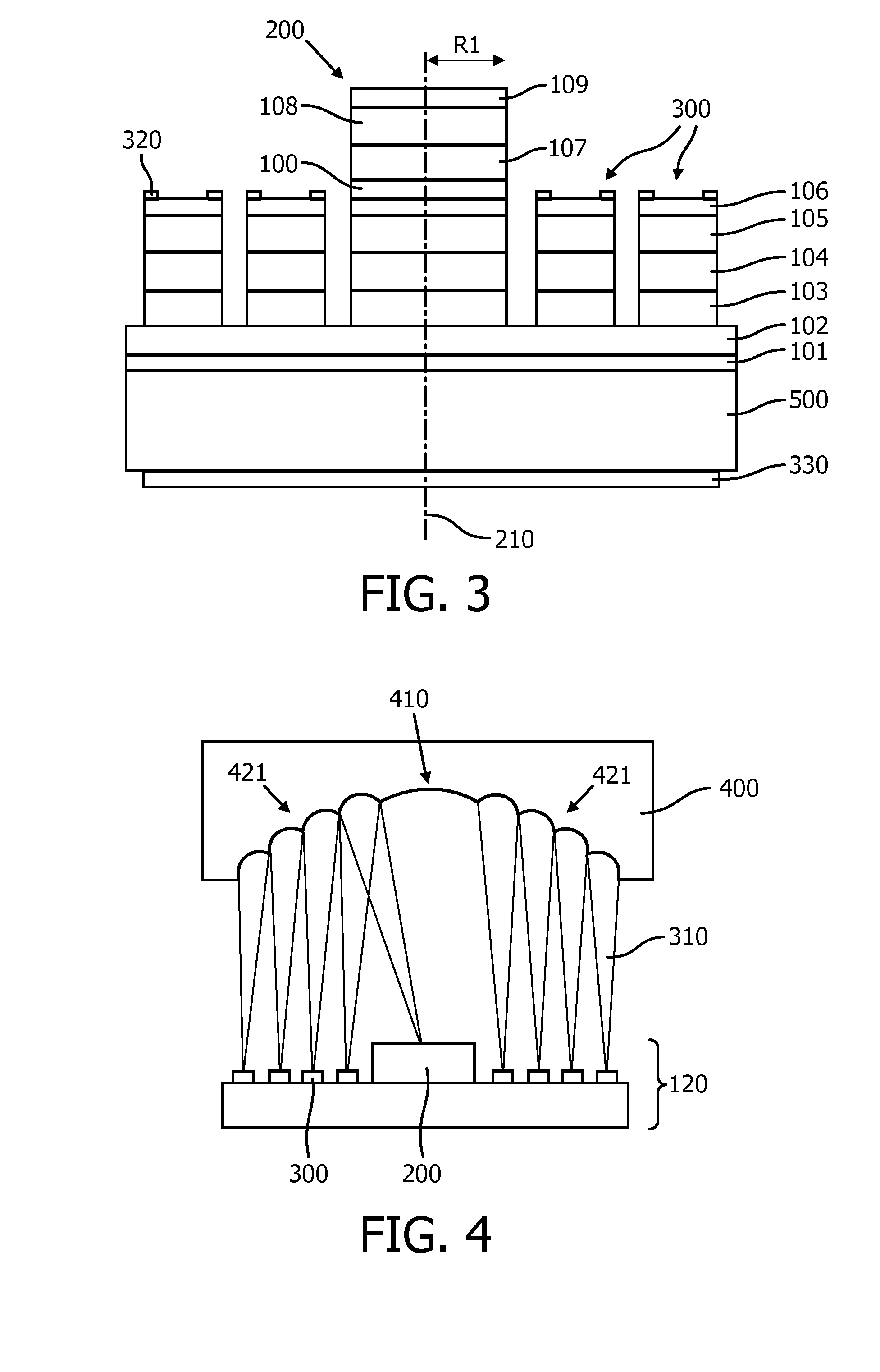
[0026]FIGS. 1 to 3 show a first example of the proposed laser device and the manufacturing thereof. In this example, the pump laser diodes are VCSELs 300 which are integrated on the same chip 120 as the VECSEL 200. The VCSELs 300 are arranged to surround the VECSEL 200. In this embodiment all semiconductor lasers are top emitting lasers as indicated in FIG. 1. A mirror element 400 (free-form optic) containing at least two radial mirror regions 410, 420 is aligned in front of the semiconductor chip 120. In this embodiment, the mirror element 400 is formed of an optically transparent body consisting of a first surface 401 facing the semiconductor chip 120 and a second surface 402. The first surface 401 is coated to provide sufficient reflectivity for the laser operation of the VECSEL 200 (R(λVECSEL)=80−99.5%) and reflection of the pump light of the VCSELs 300 as high as possible (R(λVCSEL)>95%, preferably>99%). Surface 401 is divided in two regions with different shapes.

[0027]The cent...


PUM


Abstract

The present invention relates to an optically pumped vertical external-cavity surface-emitting laser device comprising at least one VECSEL (200) and several pump laser diodes (300). The pump laser diodes (300) are arranged to optically pump the active region (108) of the VECSEL (200) by reflection of pump radiation (310) at a mirror element (400). The mirror element (400) is arranged on the optical axis (210) of the VECSEL (200) and is designed to concentrate the pump radiation (310) in the active region (108) and to form at the same time the external mirror of the VECSEL (200). The proposed device avoids time consuming adjustment of the pump lasers relative to the active region of the VECSEL and allows a very compact design of the laser device.

Description

FIELD OF THE INVENTION[0001]The present invention relates to an optically pumped vertical external-cavity surface-emitting laser device comprising at least one vertical external-cavity surface-emitting laser (VECSEL) and several pump laser diodes, wherein said pump laser diodes are arranged to optically pump an active region of the VECSEL by reflection of pump radiation at a mirror element. Vertical external-cavity surface-emitting lasers are one of the most promising high brightness laser sources and offer many advantages compared to edge-emitters, like addressable 2D-array arrangements and circular beam shapes.BACKGROUND OF THE INVENTION[0002]VECSELs typically comprise a first end mirror and an active region formed in a layer sequence, and a second end mirror arranged separated from the layer sequence and forming an external cavity of the laser. In standard setups the external cavity is composed of macroscopic optical elements, which are very bulky and need involved adjustment. By...

Claims


Application Information

Patent Timeline
IPC IPC(8): H01S5/04H01S5/183
CPCH01S5/18397H01S5/041G02B17/06H01S3/08068H01S5/0071H01S5/02476H01S5/026H01S5/141H01S5/18305H01S5/18388H01S5/423H01S5/02326
Inventor GRONENBORN, STEPHANMILLER, MICHAEL
Owner KONINKLIJKE PHILIPS ELECTRONICS NV
Why Eureka
Try Eureka