

Physical quantity detection element, physical quantity detection device, electronic apparatus, and moving object
- Summary
- Abstract
- Description
- Claims
- Application Information
AI Technical Summary
Benefits of technology
Problems solved by technology
Method used
Image

Examples
embodiment 1
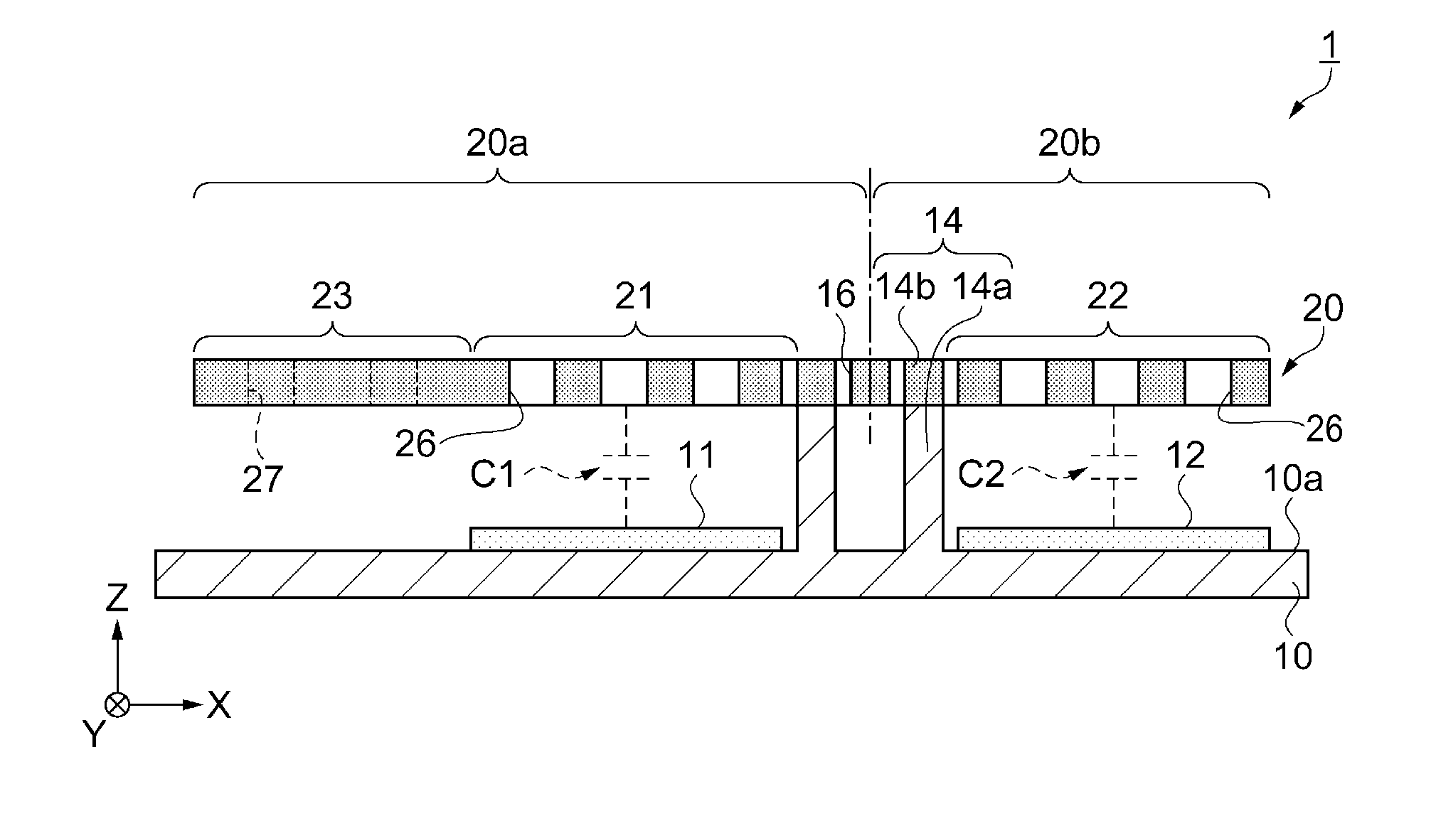
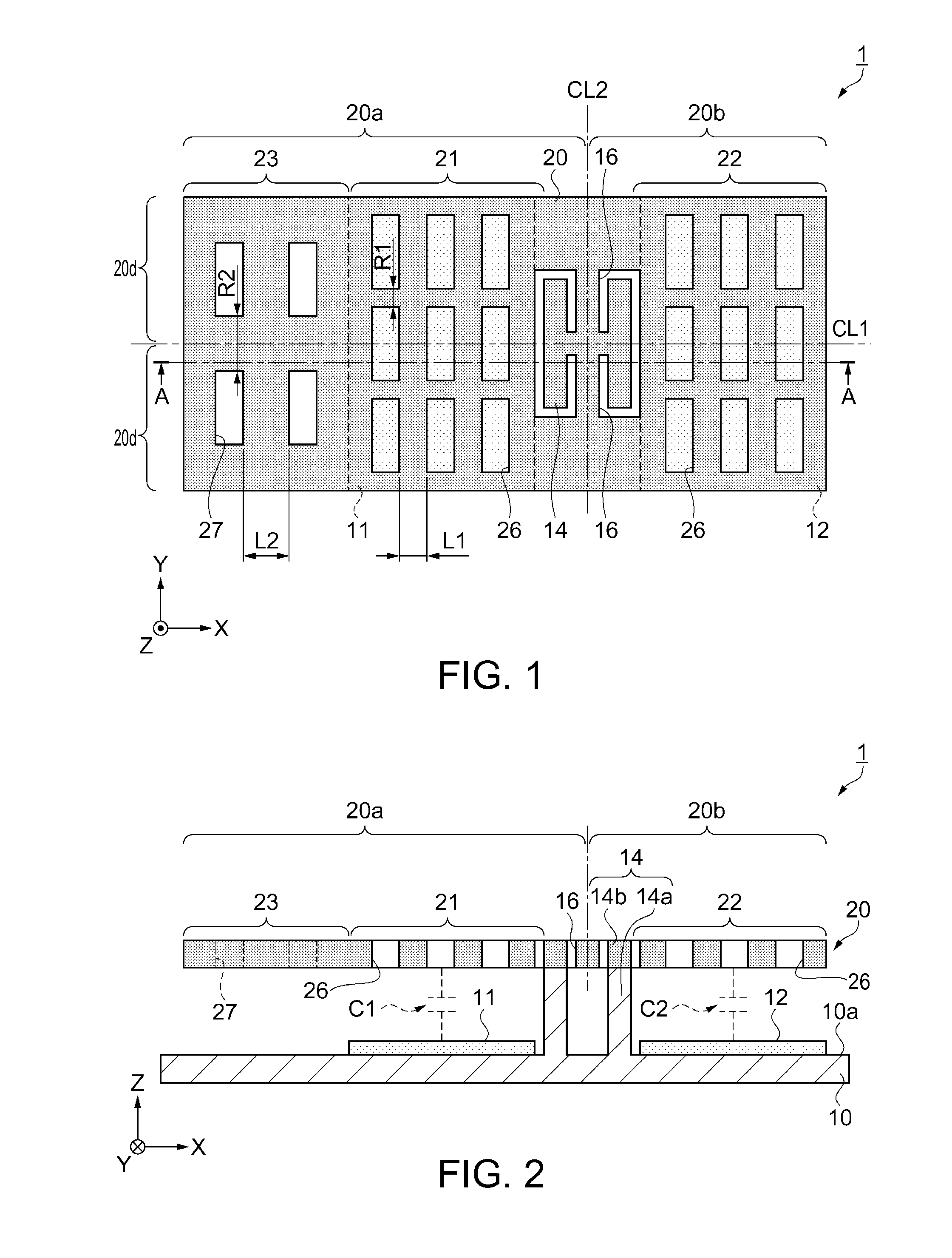
[0047]FIG. 1 is a plan view schematically showing a physical quantity detection element according to Embodiment 1. FIG. 2 is a cross-sectional view taken along line A-A in FIG. 1. Herein, in FIGS. 1 and 2, and FIGS. 3A to 9 which will be described later, an X axis, a Y axis, and a Z axis are shown as three axes orthogonal to each other, and a distal side of an arrow shown in the drawings is set as a “positive side” and a proximal side thereof is set as a “negative side”, for convenience. Hereinafter, a direction parallel with the X axis is referred to as an “X axis direction”, a direction parallel with the Y axis is referred to as a “Y axis direction”, and a direction parallel with the Z axis is referred to as a “Z axis direction”.
[0048]First, a schematic configuration of a physical quantity detection element according to Embodiment 1 will be described with reference to FIGS. 1 and 2.
[0049]A physical quantity detection element 1 of the embodiment can be used as an inertial sensor, f...
embodiment 2
[0084]FIG. 4 is a plan view schematically showing a physical quantity detection element according to Embodiment 2. FIG. 5 is a cross-sectional view taken along line A-A in FIG. 4.
[0085]The physical quantity detection element according to the embodiment will be described with reference to the drawings. The same reference numerals are used for the same constituent elements as those in Embodiment 1, and the overlapped description will be omitted. The physical quantity detection element of the embodiment is different from the configuration of Embodiment 1, in that a movable body having different thicknesses of a first mass portion and a first movable electrode portion is provided.
[0086]As shown in FIG. 4 and FIG. 5, a physical quantity detection element 2 includes the substrate 10, the first fixed electrode portion 11 and the second fixed electrode portion 12 provided on the main surface 10a of the substrate 10, a movable body 30 which is provided with a gap interposed between the movab...
modification example 1
[0094]FIG. 6 is a plan view schematically showing a physical quantity detection element according to Modification Example 1. FIG. 7 is a cross-sectional view taken along line A-A in FIG. 6.
[0095]Hereinafter, a physical quantity detection element 3 according to Modification Example 1 will be described. The same reference numerals are used for the same constituent elements as those in Embodiment 1, and the overlapped description will be omitted.
[0096]In the physical quantity detection element 3, buffer portions 50 having mass are provided on the surface of two corners formed on the first mass portion 23 on the substrate 10 side, in a plan view from the Z axis direction. As a material of the buffer portions 50, silicone having flexibility is used, in order to absorb an impact when the end portion of the first mass portion 23 comes in contact with the substrate 10. Accordingly, the mass of the first movable body 20a increases, and the position of the center of gravity is moved in the ne...
PUM
 Abstract
Description
Claims
Application Information