Method and apparatus for optical asynchronouos sampling signal measurements

a signal measurement and optical asynchronous technology, applied in the field of optical measurement, can solve the problems of complex, high cost, and difficult use, and achieve the effect of high cost, easy to use, and stable repetition frequency difference of two laser pulses

Active Publication Date: 2015-04-09
BEIHANG UNIV
View PDF1 Cites 15 Cited by
  • Summary
  • Abstract
  • Description
  • Claims
  • Application Information

AI Technical Summary

Benefits of technology

[0004]The optical asynchronous sampling technique has been applied to pump-probe, terahertz time-domain spectroscopy, distance measurement and other fields. However, the light sources used previously by researchers are two individual lasers with a specified repetition frequency difference. The two lasers require a complex electronic feedback control system to keep the frequency difference stable and maintain phase locking, which is complex, high cost and hard to use. One light source could emit two laser pulses with different repetition rates by leveraging the modal dispersion, the polarization mode dispersion, the birefringence and the chromatic dispersion in the optical resonant cavity. Due to the stability of such kinds of dispersion, the repetition frequency difference of the two laser pulses could be quite stable. Dual-repetition-frequency (dual-frequency) light source realized by using this method has the advantages of structure simplicity, easy to integrate etc., so that the optical asynchronous sampling signal measurement system is simpler and more convenient to implement.DETAILS OF THE INVENTION
[0108]The nonlinear optical device broadens the spectra of the optical pulse sequences with one or more different center wavelengths, so that the spectra of the optical pulse sequences with different center wavelengths could overlap after broadening.

Problems solved by technology

The two lasers require a complex electronic feedback control system to keep the frequency difference stable and maintain phase locking, which is complex, high cost and hard to use.

Method used


Image

  • Method and apparatus for optical asynchronouos sampling signal measurements
  • Method and apparatus for optical asynchronouos sampling signal measurements
  • Method and apparatus for optical asynchronouos sampling signal measurements

Examples


example 1

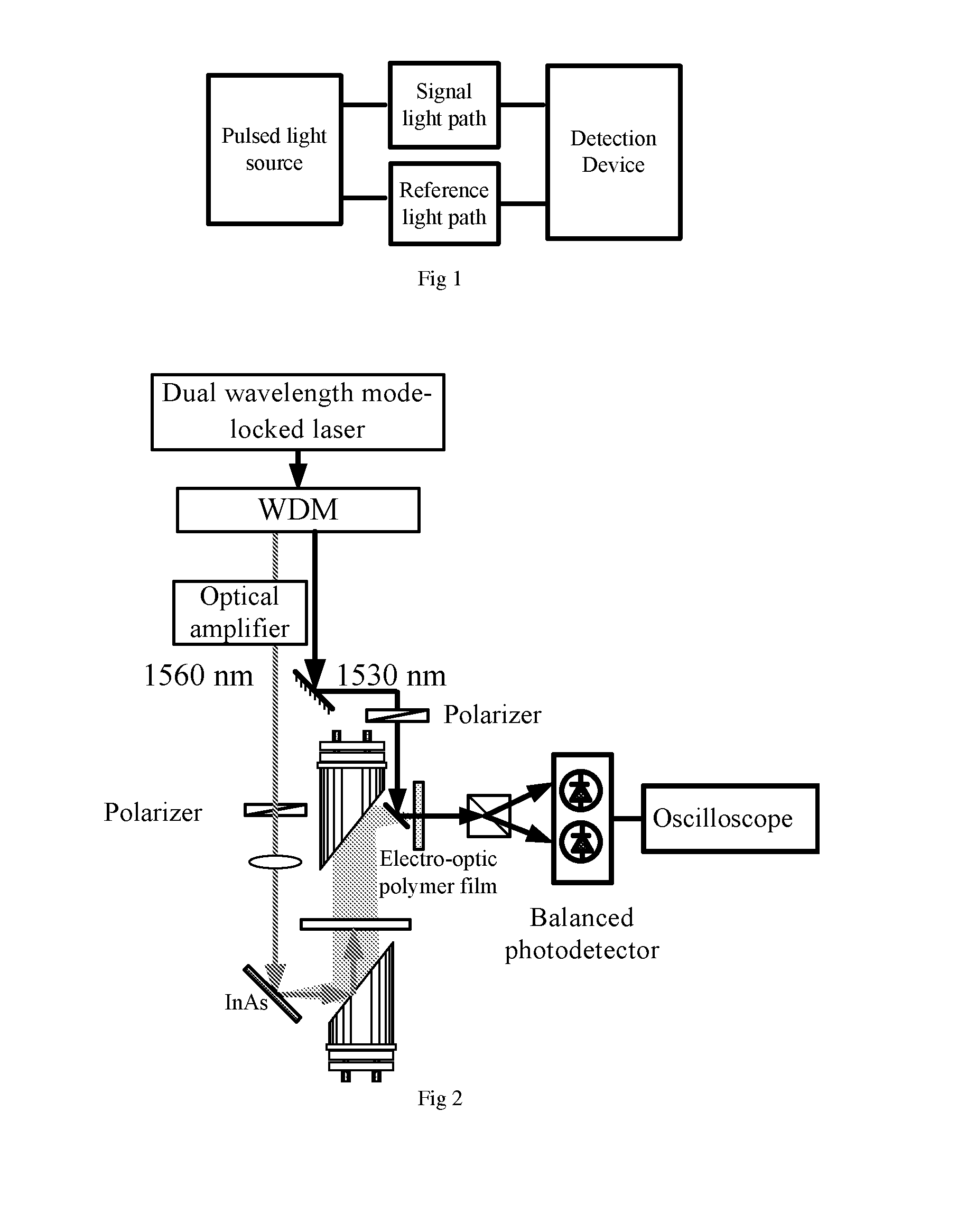
[0150]The optical asynchronous sampling signal measurement apparatus using the dual wavelength mode-locked laser for the terahertz signal measurement is shown in FIG. 2. Through a wavelength division multiplexer (WDM), the pulses with the center wavelength of 1530 nm and 1560 nm from the dual-wavelength mode-locked laser can be separated. The light pulse with the center wavelength of 1560 nm can be passed through the optical power amplifier to realize the power amplification and the pulse compression, and passed through a polarization control device to generate a horizontal-polarized pump pulse sequence. The light pulse with the center wavelength of 1530 nm can be passed through the polarization control device to generate a 45-degree linear-polarized, reference pulse sequence.

[0151]The pump optical pulse sequence can be incident at an angle of 45 degree upon the terahertz emission device—a piece of InAs crystal under external magnetic field based on the magnetic-field-enhanced Dembe...

example 2

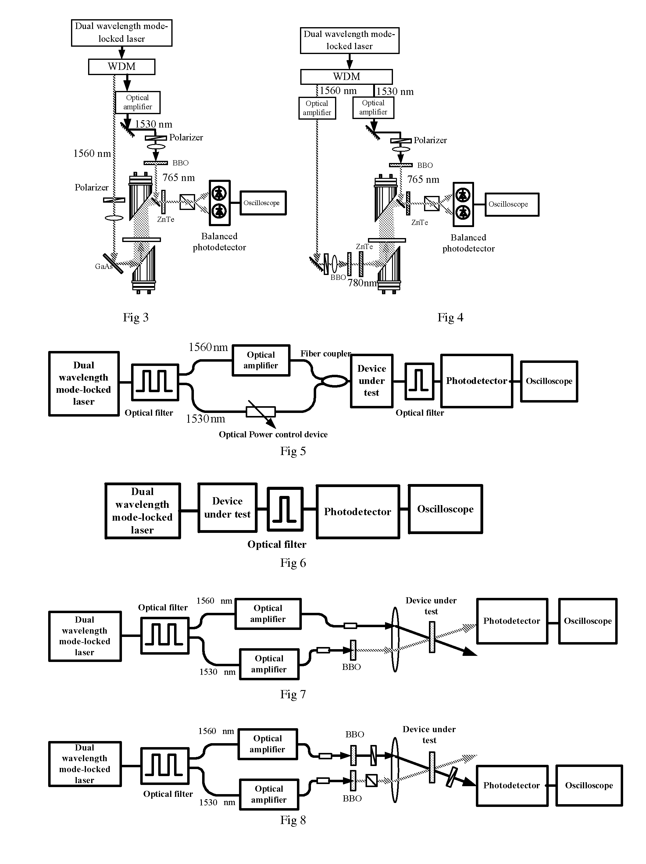
[0152]The optical asynchronous sampling signal measurement apparatus using the dual-wavelength mode-locked laser for the terahertz signal measurement is shown in FIG. 3. Through a wavelength division multiplexer, the pulses with the center wavelength of 1530 nm and 1560 nm from the dual-wavelength mode-locked laser can be separated. The light pulse with the center wavelength of 1560 nm is passed through the polarizer to generate a horizontal-polarized pump pulse sequence. The light pulse with the center wavelength of 1530 nm is passed through the optical power amplifier and the standard single mode optical fiber with the nonlinear optical effect to realize the power amplification and pulse compression, which is further incident on a frequency doubling BBO crystal to generate the frequency doubling light at 765 nm as the reference pulse sequence.

[0153]The pump optical pulse sequence is incident at an angle of 45 degree upon the terahertz emission device—the GaAs crystal, and radiates...

example 3

[0154]The optical asynchronous sampling signal measurement apparatus using the dual-wavelength mode-locked laser for the terahertz signal measurement is shown in FIG. 3. Through a wavelength division multiplexer, the pulses with the center wavelength of 1530 nm and 1560 nm from the dual-wavelength mode-locked laser is separated. The light pulse with the center wavelength of 1560 nm is passed through the optical power amplifier and the standard single mode optical fiber with the nonlinear optical effect to realize the power amplification and pulse compression, and is further incident on a frequency doubling crystal BBO crystal to generate the frequency doubling light at 780 nm as the pump light pulse sequence. The light pulse with the center wavelength of 1530 nm is passed through the optical power amplifier and the standard single mode optical fiber with the nonlinear optical effect to realize the power amplification and pulse compression, and is further incident on a frequency doub...


PUM


Abstract

A method and a system for measuring an optical asynchronous sample signal. The system for measuring an optical asynchronous sampling signal comprises a pulsed optical source capable of emitting two optical pulse sequences with different repetition frequencies, a signal optical path, a reference optical path, and a detection device. Since the optical asynchronous sampling signal can be measured by merely using one pulsed optical source, the complexity and cost of the system are reduced. A multi-frequency optical comb system using the pulsed optical source and a method for implementing the multi-frequency optical comb are further disclosed.

Description

PRIORITY CLAIM[0001]This application claims priority to PCT Patent Application No. PCT / CN2013 / 072093 published as “A method and apparatus for optical asynchronous sampling signal measurement” by Zheng Zheng et al., filed Mar. 1, 2013, which claims priority to Chinese application No. 201210052940.6 filed Mar. 2, 2012, Chinese application No. 201210052680.2 filed Mar. 2, 2012, Chinese application No. 2012100137481.1 filed May 4, 2012, Chinese application No. 2012100137119.4 filed May 4, 2012, and Chinese application No. 201210062796.9 filed Feb. 28, 2013 the specification and drawings of each of which are herein expressly incorporated by reference in their entireties.FIELD OF THE INVENTION[0002]The invention relates to the field of optical measurement, and particularly relates to a method and apparatus for optical asynchronous sampling signal measurement.BACKGROUND OF THE INVENTION[0003]Optical asynchronous sampling is a technique in which two precise frequency locked optical frequenc...

Claims


Application Information

Patent Timeline
Patent Type & Authority Applications(United States)
IPC IPC(8): G01J3/10G01J3/447G01J3/42
CPCG01J3/108G01J3/447G01J3/42G01J11/00G01J1/10G01J3/0224G01J3/0245G01J3/10G01J3/433G02F1/353G02F1/365G02F1/37G02F2203/13H01S3/0092H01S3/06791H01S3/0809H01S3/1106H01S3/1112H01S3/2391
Inventor ZHENG, ZHENGZHAO, XINLIU, LEILIU, JIANSHENG
Owner BEIHANG UNIV
Why Eureka
Try Eureka