Radar apparatus

a technology of a radar and a camera body, which is applied in the direction of instruments, measurement devices, and using reradiation, can solve the problems of increasing the cost of document 1 and the erroneous determination of the plurality of objects of the radar apparatus, and achieve the effect of accurately distinguishing a pedestrian and a vehicle from each other

Active Publication Date: 2015-04-09
TOYOTA JIDOSHA KK
View PDF10 Cites 11 Cited by
  • Summary
  • Abstract
  • Description
  • Claims
  • Application Information

AI Technical Summary

Benefits of technology

[0026]In the radar apparatus of the present invention, determination as to whether or not an object is a pedestrian is made by detecting a large change of a plurality of reflection points on the object. Therefore, the determination as to whether or not an object is a...

Problems solved by technology

Namely, even though only one object is present, the radar apparatus may erroneously determine that a plurality of objects is present.
However, the determination method of Patent Document 1 increases cost, because the method requires a camera in addition to a radar apparat...

Method used


Image

  • Radar apparatus
  • Radar apparatus
  • Radar apparatus

Examples


first embodiment

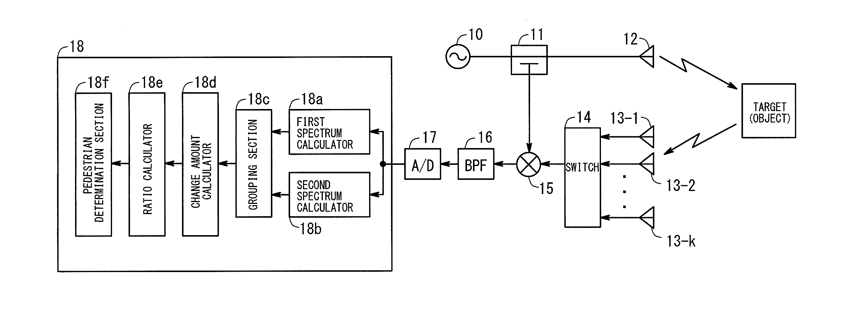
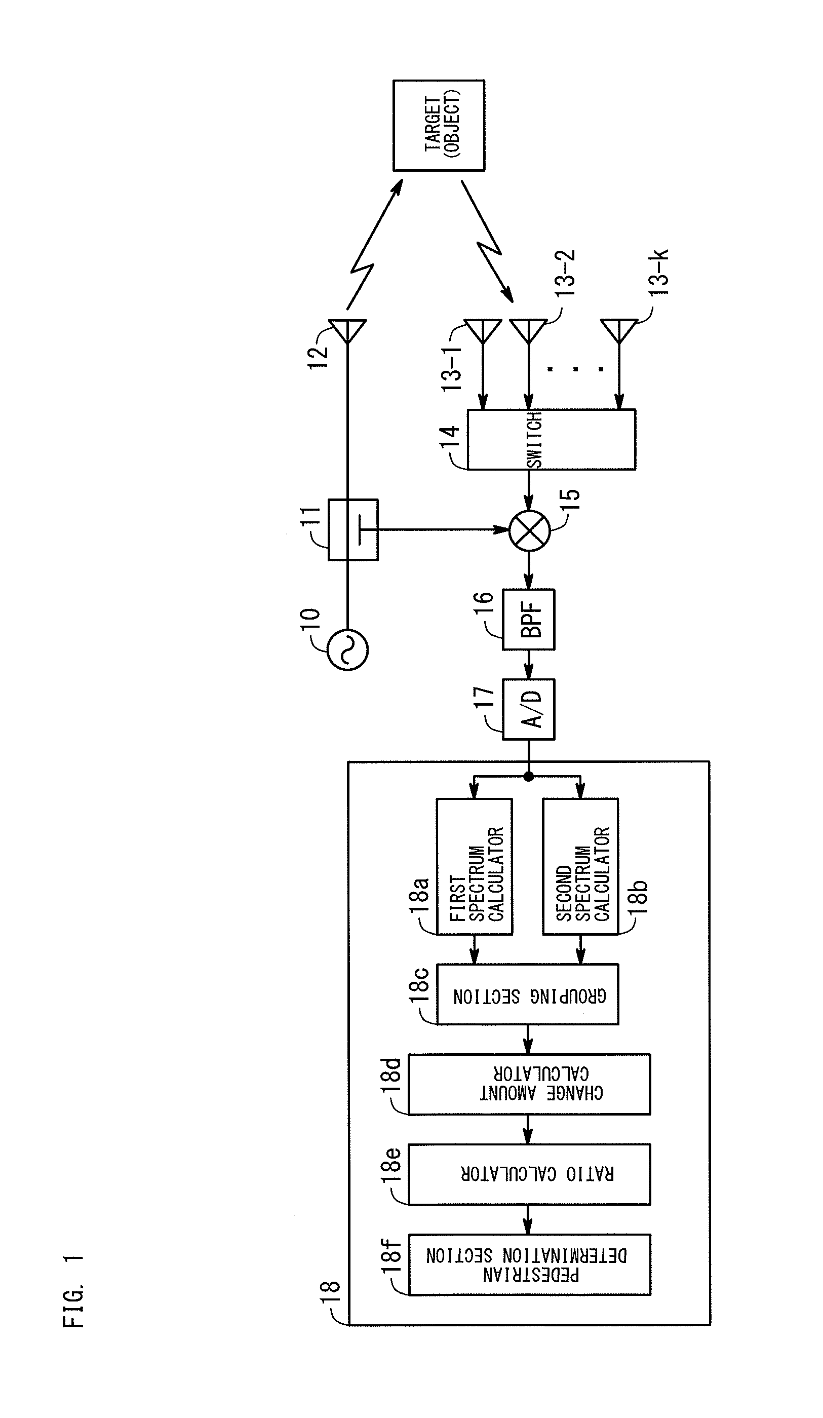
[0043]FIG. 1 is a block diagram showing the configuration of a radar apparatus according to a first embodiment. The radar apparatus of the first embodiment uses an FM-CW method for measurement of distance and velocity and uses a phase mono-pulse method for measurement of bearing. As shown in FIG. 1, the radar apparatus of the first embodiment is composed of an oscillator 10, a directional coupler 11, a transmitting antenna 12, K receiving antennas 13-1 to 13-K, a switch 14, a mixer 15, a band-pass filter 16, an AD converter 17, and a signal processing device 18.

[0044]Next, there will be described the configurations of the constituent elements of the radar apparatus of the first embodiment and its operation.

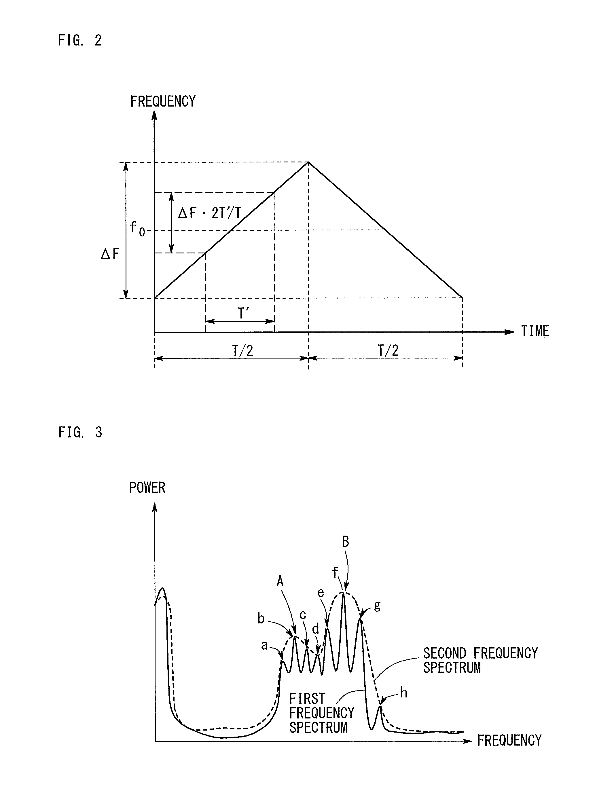
[0045]As shown in FIG. 2, the oscillator 10 oscillates a frequency-modulated signal (transmission signal). Specifically, the transmission signal is a triangular wave which has a period T, a frequency change width ΔF, and a center frequency f0. During a section of 0 to T / 2, the fre...

second embodiment

[0080]FIG. 4 is a block diagram showing the configuration of a radar apparatus according to a second embodiment. The radar apparatus of the second embodiment measures distance and velocity by a multi-frequency CW method. As shown in FIG. 4, the radar apparatus of the second embodiment has the same configuration as that of the radar apparatus of the first embodiment except that the oscillator 10 and the signal processing device 18 of the radar apparatus of the first embodiment are replaced with an oscillator 20 and a signal processing device 28, respectively.

[0081]The oscillator 20 oscillates a transmission signal whose frequency changes as shown in FIG. 5. The oscillator 20 repeats an operation of increasing the frequency of the transmission signal stepwise with time and returning the frequency to its initial value. As shown in FIG. 5, the frequency increases stepwise from f0 (initial value) to f0+Δf, then to f0+2Δf; i.e., at an increment of Δf, at time intervals t. When the number ...

third embodiment

[0091]FIG. 7 is a block diagram showing the configuration of a radar apparatus according to a third embodiment. The radar apparatus of the third embodiment performs distance measurement by a pulse method. Namely, the radar apparatus of the third embodiment measures the distance between the radar apparatus and an object from a time delay of a pulse. As shown in FIG. 7, the radar apparatus of the third embodiment has the same configuration as that of the radar apparatus of the first embodiment except that the oscillator 10 is replaced with an oscillator 30, a switch 39 is provided between the directional coupler 11 and the transmitting antenna 12, and the components and section on the output side of the mixer 15 are replaced with band-pass filters 36a and 36b, AD converters 37a and 37b, and a signal processing device 38. Portions different from those of the first embodiment are described below.

[0092]The oscillator 30 oscillates a signal of a continuous wave having a predetermined freq...


PUM


Abstract

A radar apparatus includes a change amount calculation section for obtaining, for each of a plurality of peaks of a first spectrum belonging to the same group, a peak value at the present point in time and calculating the difference between the peak value and a peak value obtained before the present point in time; a ratio calculation section for comparing the obtained difference with a predetermined difference threshold and calculating a ratio of the number of peaks whose differences are greater than the difference threshold to the number of all the peaks belonging to the same group; and a pedestrian determination section for determining that the object is a pedestrian when the calculated ratio is greater than a predetermined ratio threshold and at least one of peaks belonging to the same group differs from the remaining peaks in terms of the sign of the difference.

Description

BACKGROUND OF THE INVENTION[0001]1. Field of the Invention[0002]The present invention relates to a radar apparatus which can measure a distance to an object and which can determine whether or not the object is a pedestrian. Notably, the term “pedestrian” used herein encompasses not only a pedestrian but also a person in an automobile or the like.[0003]2. Background Art[0004]A radar apparatus is known as an apparatus for detecting an object. The radar apparatus radiates a radio wave toward an object, receives a reflection wave from the object, and detects the distance to the object and the velocity and bearing of the object. Examples of known methods for measurement of distance and velocity include a FM-CW method, a multi-frequency CW method, and a pulse method. Examples of known methods for measurement of bearing include a digital beam forming method and a phase mono-pulse method. In recent years, radar apparatuses are mounted on automobiles, etc., and are used for controlling the d...

Claims


Application Information

Patent Timeline
IPC IPC(8): G01S13/04
CPCG01S13/04G01S7/41G01S13/06G01S13/28G01S13/34
Inventor NAKAI, MAKOTOMATSUZAWA, SHIN-ICHIROMINAMI, YOSHIAKIODA, YUJI
Owner TOYOTA JIDOSHA KK
Why Eureka
Try Eureka