Expandable spinal implant

a spinal implant and expandable technology, applied in the field of expandable spinal implants, can solve the problems of additional screws or locking elements, inconvenient post insertion manipulation, and inability to fit the adjacent vertebrae being spaced, etc., and achieve the effect of increasing the height of the devi

Active Publication Date: 2015-04-09
SPINAL ELEMENTS INC
View PDF12 Cites 45 Cited by
  • Summary
  • Abstract
  • Description
  • Claims
  • Application Information

AI Technical Summary

Benefits of technology

[0010]An expandable implant device for insertion between two vertebrae is disclosed. The device has an upper body, a lower body and an external retainer band. The upper body has an interior surface forming a hollow cavity and an exterior surface having a plurality of ratchet teeth sloped to allow upward movement. The lower body has an interior surface forming a hollow cavity and an exterior surface having a plurality of ratchet teeth sloped to allow downward movement. The external retainer band holds the upper body and lower body and has an inner surface having a plurality of upper ratchet teeth sloped for allowing upward movement and a plurality of lower ratchet teeth for allowing downward movement. The ratchet teeth of the upper body are mated or fitted to the upper teeth of the retainer band and the ratchet teeth of the lower body are mated or fitted to the lower ratchet teeth of the retainer band. The height of the device is increased by upward movement of the upper body and downward movement of the lower body. The movement is linear and maintained parallel to the ratchet teeth as the bodies move relative to the retainer band. The remaining ratchet teeth mated or fitted to the ratchet teeth of the retainer are locked to resist compressive movement of the extended upper and lower bodies. The retainer band has at least one end with a slotted opening. The upper body and lower body are spaced and separated by the retainer band. The vertical movement of the bodies is parallel and horizontal relative to the vertebrae being spaced. The movement of the upper and lower bodies increases a hollow cavity size or volume formed by the retainer band and spaced apart bodies.

Problems solved by technology

One of the problems of such devices is the amount of post insertion manipulation required to reach a fully expanded properly space height is tedious and time consuming.
Secondly, additional set screws or locking elements are often required to keep the device at its proper size.
Thirdly, the devices of a circular shape are not the best fit for the adjacent vertebrae being spaced.
Fourth, most of the devices have the internal space occupied with mechanisms limiting the amount of bone growth material available for packing the implants.
This places localized high loading between the vertebrae because the wedge surfaces are not parallel to the vertebrae.

Method used


Image

  • Expandable spinal implant
  • Expandable spinal implant
  • Expandable spinal implant

Examples


Embodiment Construction

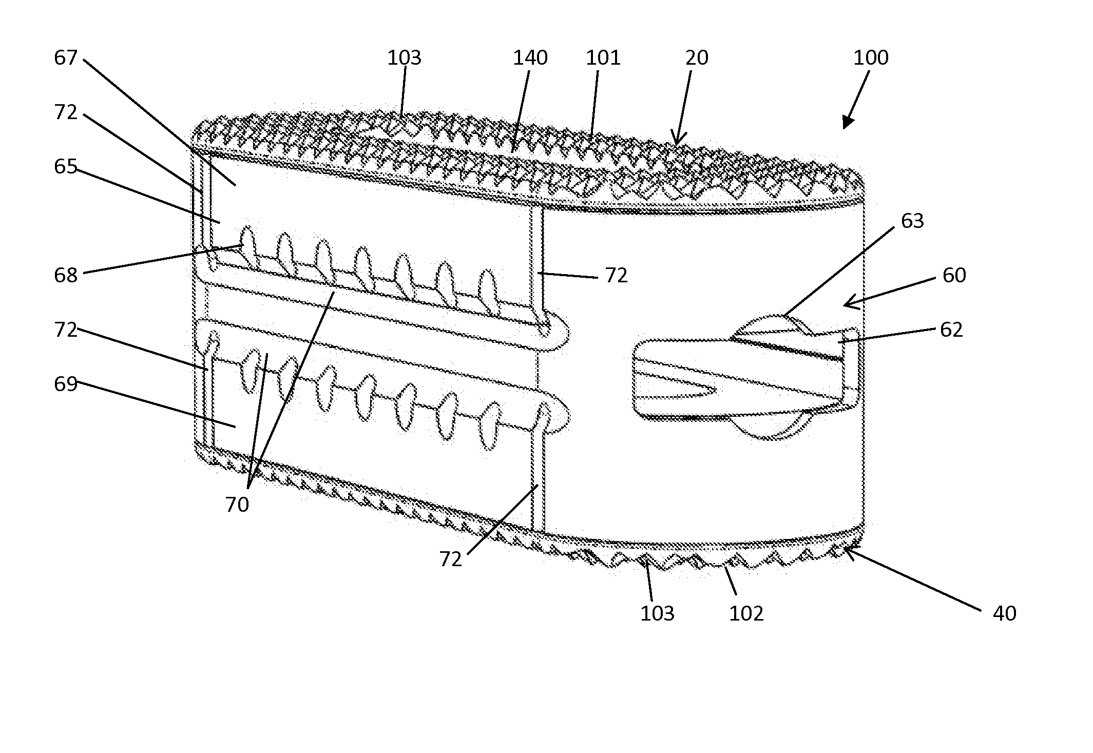
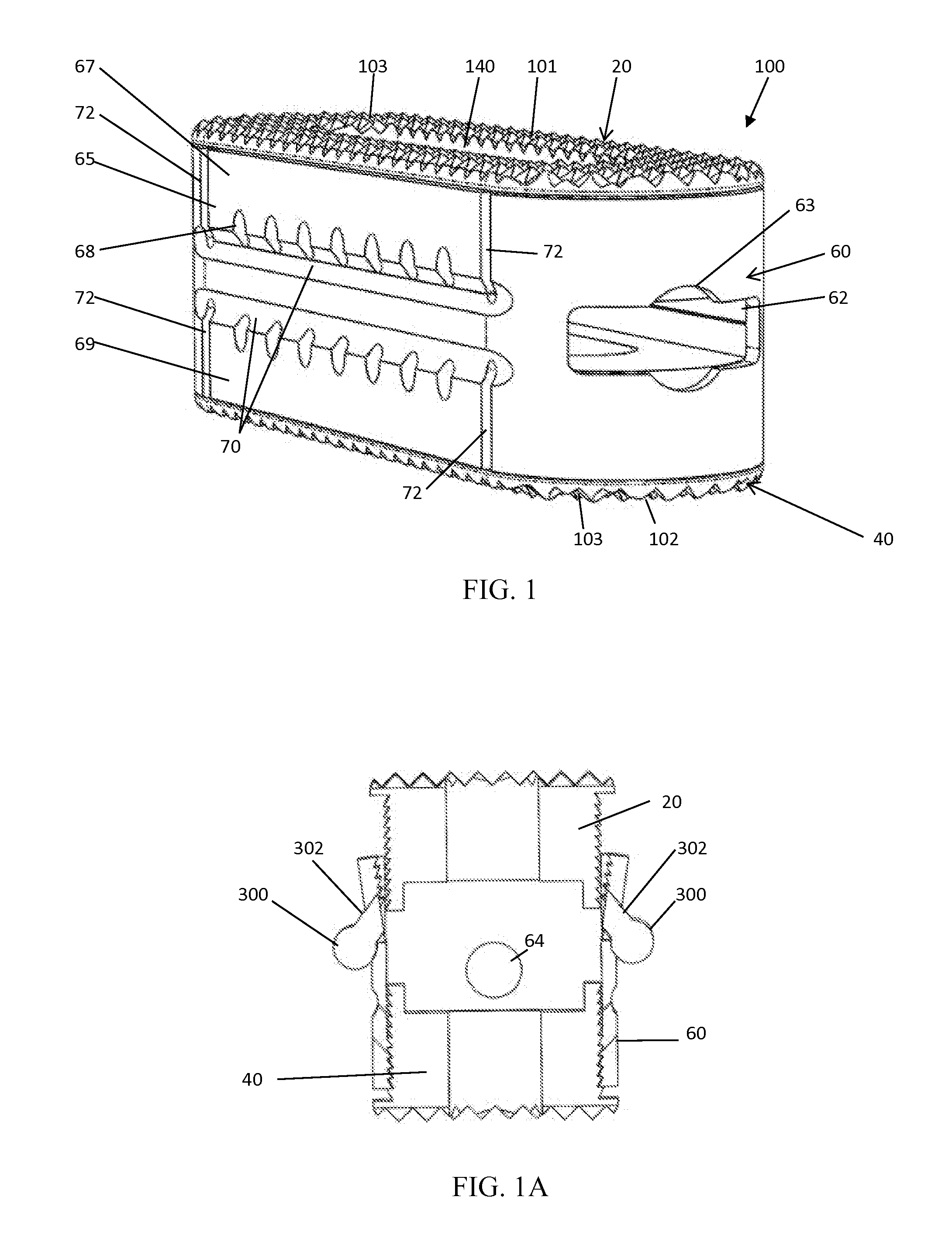
[0026]With reference to FIG. 1, the expandable implant device 100 made according to the present invention is illustrated. As shown, the implant device 100 is in the fully refracted unexpanded condition. As shown, the device 100 has an upper body 20, a lower body 40 and a retainer band 60 encircling both the upper and lower body. In a preferred embodiment, the upper and lower bodies are made of a plastic or synthetic material. In a preferred embodiment, this material is PEEK (PolyEtherEtherKetone) although alternative materials can be used for either of the upper or lower body. The top outer surface 101 of the upper body 20 and the bottom outer surface 102 of the lower body 40 are provided with a plurality of facets or ridges 103 or roughened surfaces. These surfaces 101, 102 will contact the vertebrae when installed and expanded and provide a gripping surface to which the implant is securely held when expanded between the two spaced vertebrae.

[0027]As shown, the expandable implant d...


PUM


Abstract

An expandable implant device (100) for insertion between two vertebrae (400) is disclosed. The device (100) has an upper body (20), a lower body (40) and an external retainer band (60). The external retainer band (60) holds the upper body (20) and lower body (40) and has an inner surface having a plurality or set of upper ratchet teeth (80U) sloped for allowing upward movement and a plurality or set of lower ratchet teeth (80L) for allowing downward movement. The ratchet teeth (80) of the upper body (20) are mated or fitted to the upper teeth (80) of the retainer band (60) and the ratchet teeth (82) of the lower body (40) are mated or fitted to the lower ratchet teeth (82) of the retainer band (60). The height of the device (100) is increased by upward movement of the upper body (20) and downward movement of the lower body (40).

Description

TECHNICAL FIELD[0001]The present invention relates to spinal implants generally, more particularly to an improved expandable spinal implant.BACKGROUND OF THE INVENTION[0002]Spinal stabilization can be achieved by providing an interbody implant. Some of these implants are bone, PEEK, solid titanium or similar non-bone implant material and some are hollow implants that provide for inclusion of a bone graft or other suitable material to facilitate bony union of the vertebrae.[0003]Interbody implants can be inserted into the disc space through an anterior, posterior or lateral approach. In some systems, the implants are inserted into a bore formed between adjacent vertebral bodies in the cortical endplates and can extend into the cancellous bone deep to the cortical endplates. Implant size is typically selected such that the implants force the vertebrae apart to cause tensing of the vertebral annulus and other soft tissue structures surrounding the joint space. Tensing the soft tissues ...

Claims


Application Information

Patent Timeline
Patent Type & Authority Applications(United States)
IPC IPC(8): A61F2/44A61F2/46
CPCA61F2/447A61F2002/30579A61F2/4611A61F2/4455A61F2002/30522A61F2002/30556
Inventor WHIPPLE, DALE
Owner SPINAL ELEMENTS INC
Why Eureka
Try Eureka