Automated roughneck

a roughneck and automatic technology, applied in the direction of drilling casings, drilling pipes, borehole/well accessories, etc., can solve the problems of unintended disconnection and the suspension of drilling operations

Active Publication Date: 2015-04-16
NABORS SERVICES
View PDF5 Cites 50 Cited by
  • Summary
  • Abstract
  • Description
  • Claims
  • Application Information

AI Technical Summary

Benefits of technology

[0006]The present disclosure provides for an automated roughneck. The automated roughneck may be used for connecting and disconnecting threadedly coupled tubular members of a tubular string. The automated roughneck may include a backup tong. The backup tong may have a central opening adapted to receive the tubular string. The backup tong may include a backup tong housing. The backup tong housing may include a backup tong housing door removably coupled to the backup tong housing. The backup tong housing door may be adapted to allow the backup tong to be radially installed or removed from the tubular string. The backup tong may also include a gripper assembly. The gripper assembly may be coupled to the backup tong housing. The gripper assembly may include a plurality of gripper jaws adapted to extend radially inwardly into the central opening and engage the outer surface of a first tubular member and prevent the rotation of the first tubular member. The gripper assembly may be to be selectively separable into at least two gripper subunits. The automated roughneck may further include a makeup tong. The makeup tong may be positioned generally parallel with the backup tong. The makeup tong may have a central opening generally collinear with the central opening of the backup tong. The makeup tong may be coupled to and movable relative to the backup tong. The makeup tong may include a makeup tong housing. The makeup tong housing may include a makeup tong housing door removably coupled to the makeup tong housing adapted to allow the makeup tong to be radially installed or removed from the tubular string. The makeup tong may further include a spinner assembly. The spinner assembly may be coupled to the makeup tong housing. The spinner assembly may include a plurality of spinner jaws adapted to extend radially inwardly into the central opening and engage an outer surface of a second tubular member. The spinner assembly may be adapted to be rotatable relative to the makeup tong housing to rotate the second tubular member. The spinner assembly may be adapted to be selectively separable into at least two spinner subunits. The makeup tong may further include a drive assembly. The drive assembly may be generally annular in shape and adapted to house the spinner assembly in an interior thereof. The drive assembly may be adapted to be rotated by one or more spinner motors coupled to the makeup tong housing. The drive assembly may be coupled to the spinner assembly and adapted to rotate the spinner assembly relative to the makeup tong housing. The drive assembly may include a removable segment rotatably positionable in alignment with the makeup tong housing door of the makeup tong housing to allow the drive assembly to be radially removable from the tubular string.
[0007]The present disclosure also provides for a method for removing an automated roughneck from a drill string while the drill string remains in place. The method may include providing an automated roughneck. The automated roughneck may include a backup tong. The backup tong may have a central opening adapted to receive the tubular string. The backup tong may include a backup tong housing. The backup tong housing may include a backup tong housing door removably coupled to the backup tong...

Problems solved by technology

Such an unintended disconnection may result in costly and time-consuming “fishing” operations to retrieve the disconnected section of drill pipe, during which drilling operations must be suspended....

Method used


Image

  • Automated roughneck
  • Automated roughneck
  • Automated roughneck

Examples


Embodiment Construction

[0040]It is to be understood that the following disclosure provides many different embodiments, or examples, for implementing different features of various embodiments. Specific examples of components and arrangements are described below to simplify the present disclosure. These are, of course, merely examples and are not intended to be limiting. In addition, the present disclosure may repeat reference numerals and / or letters in the various examples. This repetition is for the purpose of simplicity and clarity and does not in itself dictate a relationship between the various embodiments and / or configurations discussed.

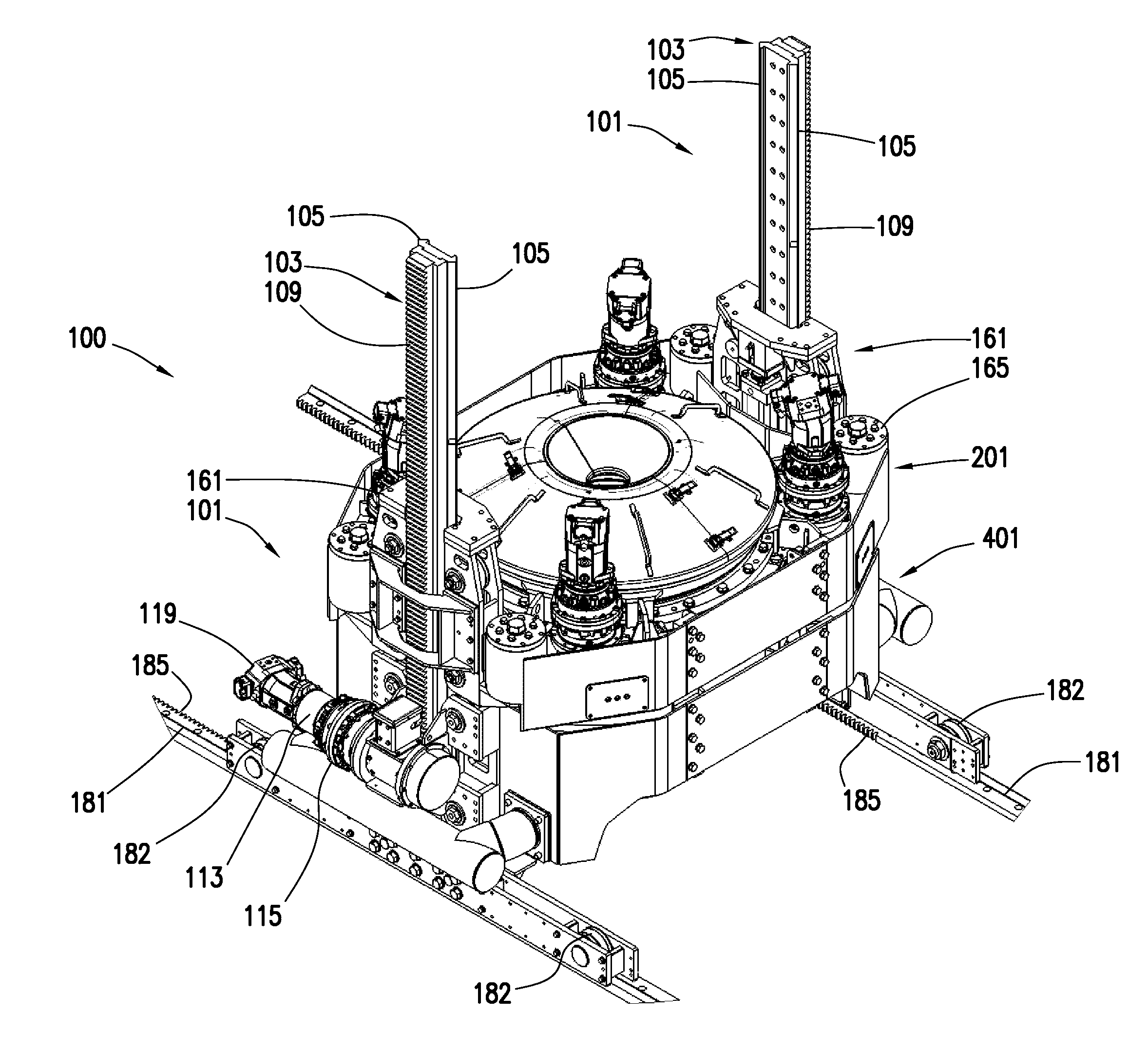
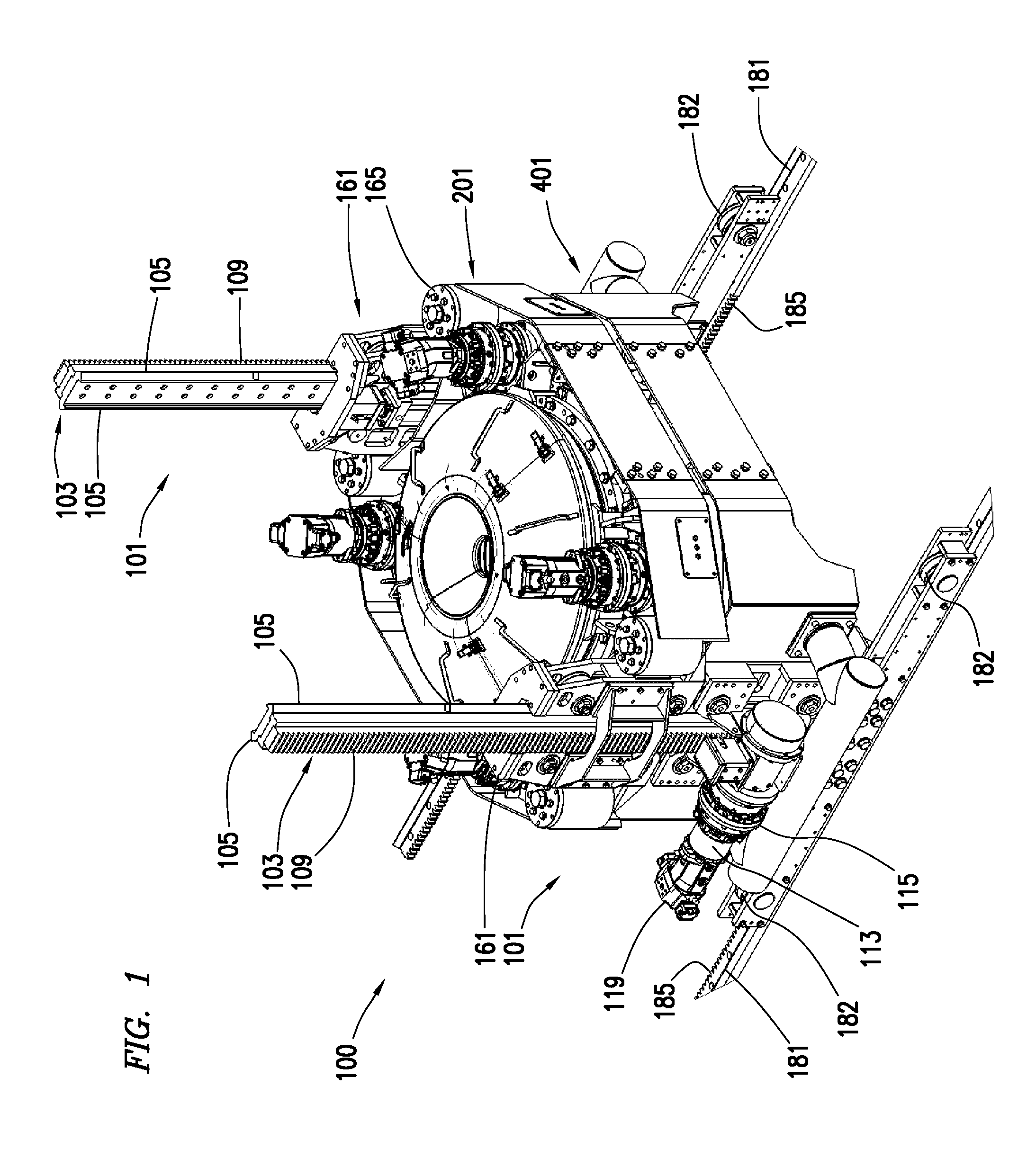
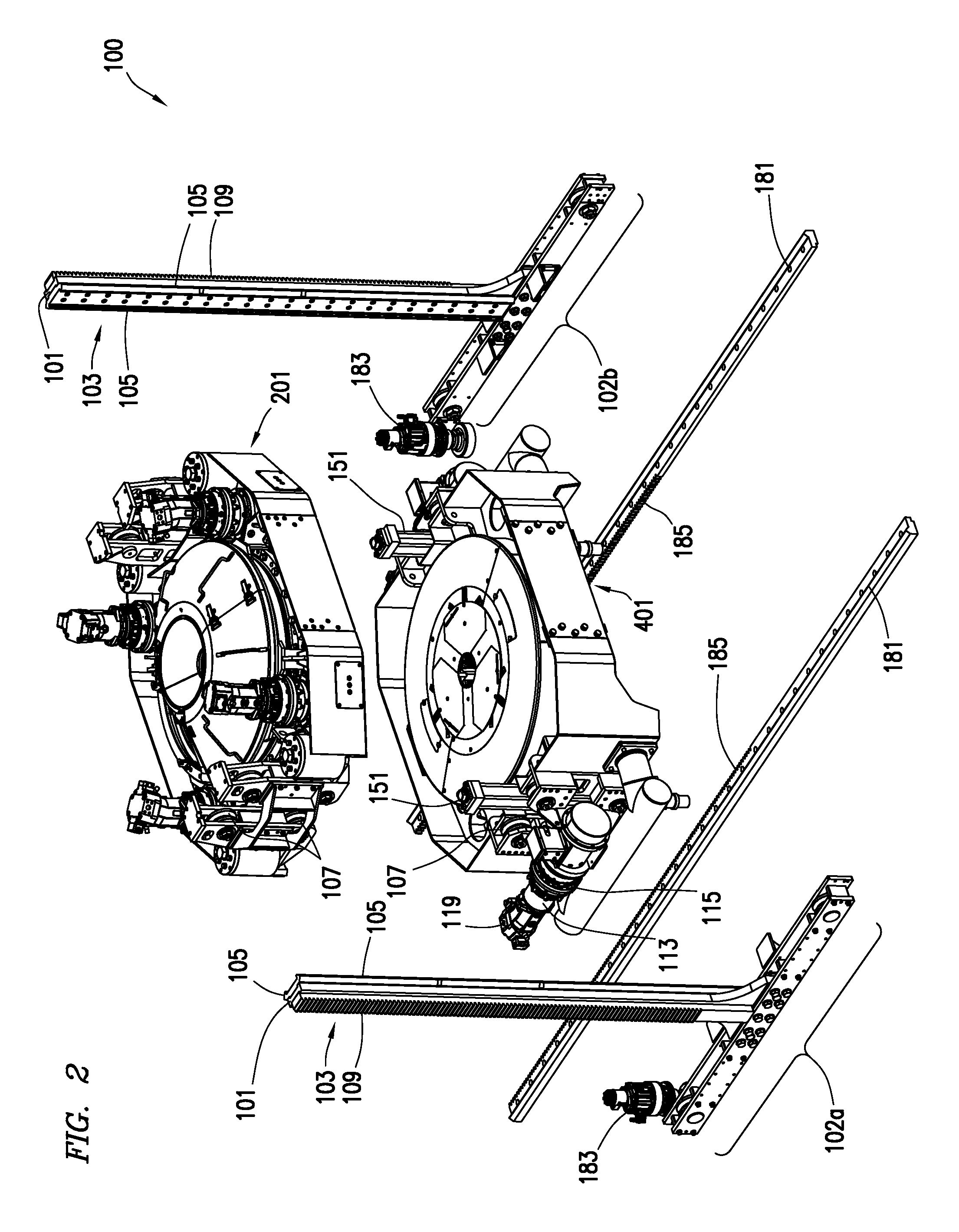
[0041]In some embodiments of the present disclosure as depicted in FIGS. 1-5, automated roughneck 100 may include frame 101, makeup tong 201, and backup tong 401. In some embodiments, frame 101 may include one or more uprights 103. Uprights 103 may be adapted to, for example and without limitation, connect makeup tong 201 with backup tong 401. In some embodiments, for ...


PUM


Abstract

An automated roughneck may include a backup tong and a makeup tong. The makeup tong and backup tong may be selectively movable relative to one another. The makeup tong and backup tong may include spinner and gripper assemblies respectively adapted to make up and break out threaded connections. The automated roughneck may be configurable to be removable from the drill string in a lateral direction.

Description

CROSS-REFERENCE TO RELATED APPLICATIONS[0001]This application is a nonprovisional application which claims priority from U.S. provisional application No. 61 / 885,381, filed Oct. 1, 2013.TECHNICAL FIELD / FIELD OF THE DISCLOSURE[0002]The present disclosure relates generally to making-up and breaking out threadedly connected tubular members, and more particularly to an automated device and associated methods for making up and breaking out tool strings.BACKGROUND OF THE DISCLOSURE[0003]In many stages of the drilling and completion of an oil and gas well, tubular members are coupled end-to-end to form what is known as a string. For the purposes of this disclosure, the term “drill string” will be used to refer to any such string, including without limitation drill strings, tool strings, casing strings, and completion strings. Typically, tubular members are made up in approximately 30-90 foot segments known as pipe stands, and include threaded couplings at each end. Commonly known as “box” a...

Claims


Application Information

Patent Timeline
IPC IPC(8): E21B17/042E21B17/00E21B19/16
CPCE21B17/042E21B19/164E21B17/006E21B19/165
Inventor GUPTA, ASHISHSCEKIC, VLADIMIRREDDY, PADIRAELLIS, BRIANYOUSEF, FAISALMAGNUSON, CHRISHEIGHINGTON, LARRY
Owner NABORS SERVICES
Why Eureka
Try Eureka