
Water barrier for submarine power cable

a technology of water barrier and power cable, which is applied in the direction of power cables, pin insulators, conductors, etc., can solve the problems of poor fatigue properties, damage to the cables, water ingress in the cables, etc., and achieve the effect of less prone to fatigu

Active Publication Date: 2015-04-16
NEXANS
View PDF24 Cites 5 Cited by
  • Summary
  • Abstract
  • Description
  • Claims
  • Application Information

AI Technical Summary

Benefits of technology

The patent describes a cable that is both waterproof and flexible, which reduces its chances of getting tired easily. This cable is ideal for use in submarines.

Problems solved by technology

Such cables are exposed to harsh environments that may cause damage to the cables if they are not sufficiently protected against water ingress and mechanical force or pressure loads.
One problem with submarine power cables with metal sheath used for dynamic applications is that they are stiff and vulnerable to movements resulting in poor fatigue properties.
A cable that is constantly moving and exposed external dynamic forces will at some point experience possible fatigue fracture on the outer sheath resulting in possible water ingress in the cable.
Said metal sheath will protect a cable from water ingress, but will make the cable less flexible and thus less usable for dynamic applications.
This construction will protect the inner core from water ingress, but the cable will have degraded flexibility, and as mentioned flexibility is an important factor when used in dynamic installations.
High voltage cables comprising a metallic barrier and having good flexible properties for application in dynamic installations have been a big issue and challenge for cable manufactures.

Method used


Image

  • Water barrier for submarine power cable
  • Water barrier for submarine power cable

Examples


Embodiment Construction

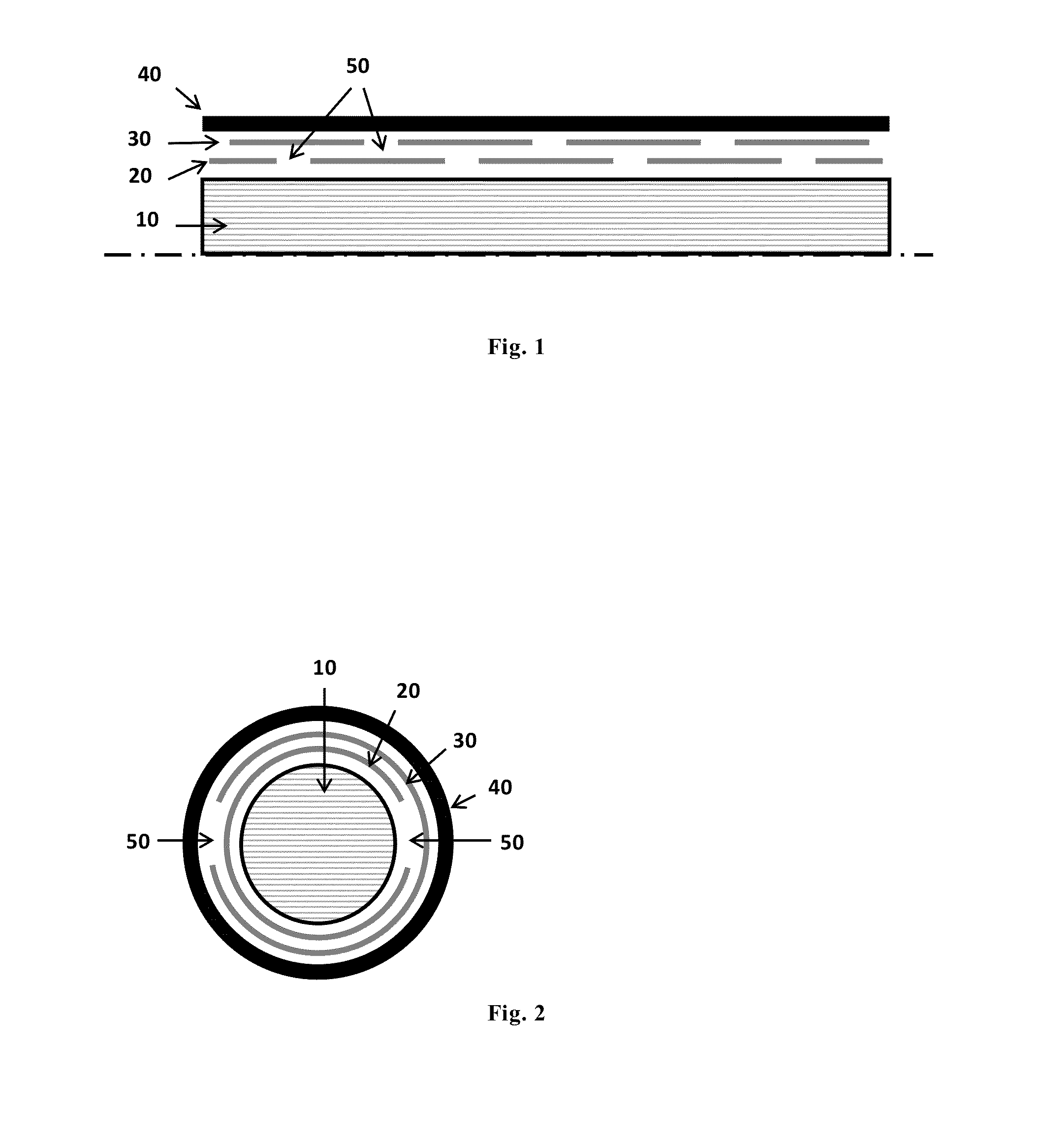
[0024]FIG. 1 shows only one half of a part of the cable cut along the lower dotted line in the figure, while FIG. 2 shows a cross section of a complete cable.

[0025]The cable comprises a cable core 10 which is the main element of the cable enabling transportation of power. The cable core 10 is coated with an insulator system (not shown). This insulator system typically comprises a conductor screen, insulation and insulation screen. The cable core 10 with its insulator system is further enclosed in protective water barrier layers and an outer sheath.

[0026]In one embodiment the protective water barriers comprises a first and second protective layers 20, 30. These are made of metal tape that is helically wound to the cable core 10 with small gaps 50 between each turn.

[0027]The gaps 50 between each turn can vary between 1-10 mm. In one preferred embodiment the gaps 50 are 5 mm wide.

[0028]The first protective layer 20 is closest to the core 10 and the second protective layer 30 is wound t...


PUM


Abstract

An cable that is flexible and watertight by means of a metallic water resistant barrier has at least two protective layers 20, 30 of metal tape wound to a cable core 10 with small gaps 50 between each turn of the tape, and where each layer is displaced 50% relative to each other thus covering the gaps in the layers 20, 30, and where the gaps 50 are filled with a water resistant material.

Description

RELATED APPLICATION[0001]This application claims the benefit of priority from European Patent Application No. 13 306 409.7, filed Oct. 15, 2013, the entirety of which is incorporated by reference.BACKGROUND[0002]1. Field of the Invention[0003]The present invention relates to electrical power cables. More specifically the invention relates to a flexible and watertight metallic water barrier for a submarine power cable.[0004]2. Description of Related Art[0005]Submarine cables applied for different purposes are well known in the art. Such cables are exposed to harsh environments that may cause damage to the cables if they are not sufficiently protected against water ingress and mechanical force or pressure loads.[0006]Different types of submarine cables exist, e.g. cables for carrying signals and cables for carrying high voltages. Electrical high voltage cables are categorized as medium, high and extra high voltage (MV, MH, EHV) power cables. They are typically designed with a cable co...

Claims


Application Information

Patent Timeline
IPC IPC(8): H01B7/282H01B7/285
CPCH01B7/2825H01B7/285H01B7/045Y02A30/14
Inventor OLSEN, ESPEN
Owner NEXANS
Learn More