Latching mechanisms for clamshell type couplers
a technology of latching mechanism and clamshell, which is applied in the field of latching mechanism used in clamshell type couplers, can solve the problems of electrical spark hazard, instantaneous combustion, and electrical charge may rise, and achieve the effects of preventing electrostatic buildup, ensuring safety, and ensuring safety
- Summary
- Abstract
- Description
- Claims
- Application Information
AI Technical Summary
Benefits of technology
Problems solved by technology
Method used
Image
Examples
first embodiment
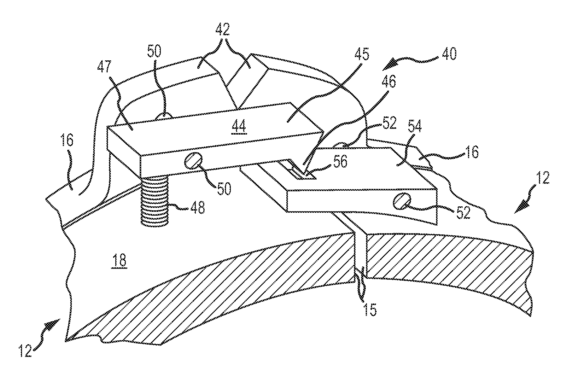
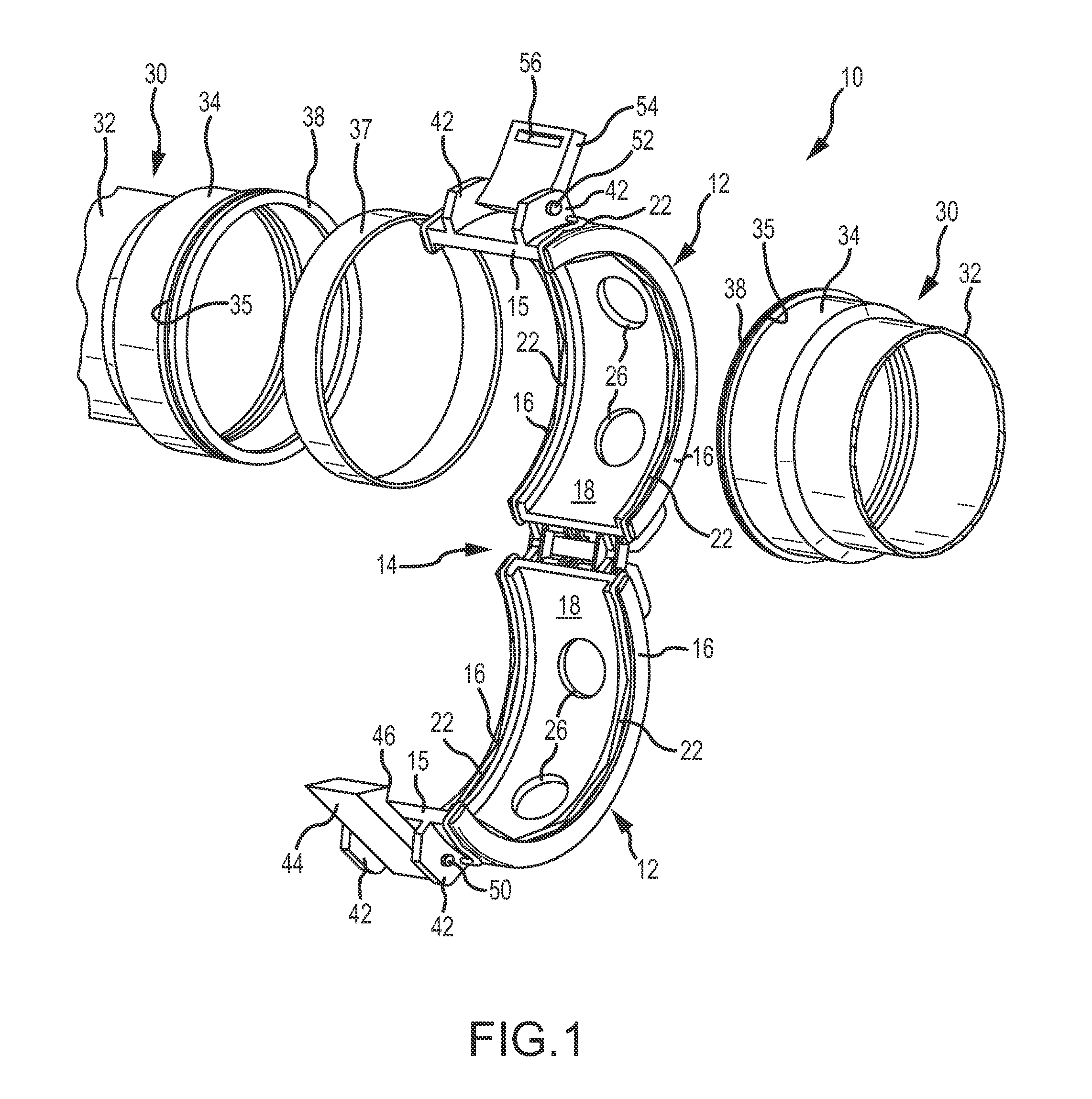
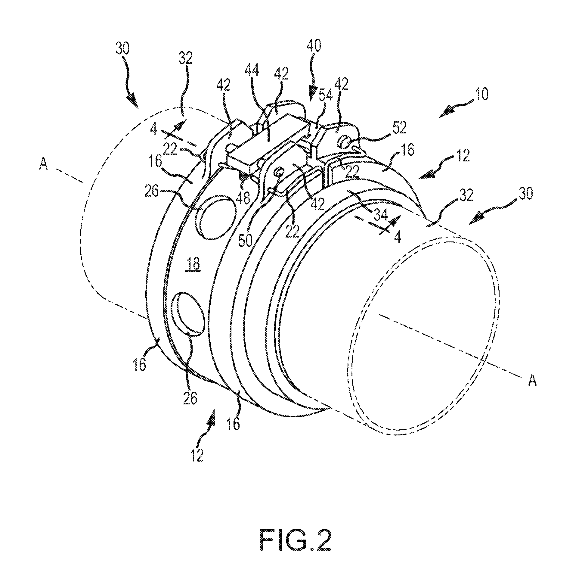
[0040]Referring to the drawings, and particularly to FIGS. 1-4, a threadless, clamshell type coupling assembly or coupler is illustrated in a first embodiment, and is generally indicated at 10. The coupling assembly comprises a pair of coupling halves 12 that are connected to one another along hinge 14. Each of the coupling halves 12 terminate along respective longitudinally extending faces 15. These faces define the free ends of the coupling halves that are placed in a confronting position to close the coupling and to thereby secure confronting ends of the fluid conveying members 30. A latching mechanism 40 is provided to positively and selectively lock the coupling halves to one another in a closed or coupled position. As shown, the coupling halves 12 are curved or arcuate in shape, and traverse an arc of approximately 180°.
[0041]The threadless clamshell type coupling assembly illustrated is especially adapted for use in fluid conveying applications, such as low pressure aircraft ...
second embodiment
[0048]Referring to FIGS. 5-7, a latching mechanism 40 is illustrated in a A general principle of operation for this embodiment is the use one or more spring-loaded buttons that can be used to positively engage and lock the coupling assembly. Referring to FIGS. 6 and 7, the latching mechanism 40 includes a base or mount portion 64 mounted to a first coupling half and located between the respective latching mounts 42. Two extensions or tongues 60 extend circumferentially beyond the face 15 of the first coupling half towards the second coupling half. A latching hole 62 is formed in each of the extensions 60 as shown. The second coupling half includes a latching housing 66 with a pair of latching openings 68 sized and oriented for receiving the extensions 60. Each of the openings 68 communicate with a biased locking button 70 that may be manipulated by the user to lock and unlock the latching mechanism. Referring specifically to FIG. 7, one particular construction for the biased lockin...
fourth embodiment
[0051]Referring to FIGS. 11-13, a fourth embodiment is illustrated for the latch mechanism 40. This embodiment is characterized by a single latching arm 120 rotatably mounted on a pin 124 that traverses between adjacent latching mounts 42. The latching arm 120 includes a central rod or core 126, with a proximal end thereof having an opening to receive the mounting pin 124. A retention spring 128 is placed over the distal end of the central rod 126, and resides between the proximal end of the central rod 126 and a movable bushing 130 mounted over the central rod 126 distally of the spring 128. A spacer 132 is also placed over the distal end of the central rod 126, and resides distally of the movable bushing 130. A head or cap 122 attaches to the distal end of the rod 126. The movable bushing 130 may be selectively slid proximally along the central rod 126, thereby compressing the spring 128. The normal, biased position of the movable bushing 130 is shown in FIG. 12, in which the mova...
PUM
 Abstract
Description
Claims
Application Information
 - R&D
- Intellectual Property
- Life Sciences
- Materials
- Tech Scout
- Unparalleled Data Quality
- Higher Quality Content
- 60% Fewer Hallucinations
Browse by: Latest US Patents, China's latest patents, Technical Efficacy Thesaurus, Application Domain, Technology Topic, Popular Technical Reports.
© 2025 PatSnap. All rights reserved.Legal|Privacy policy|Modern Slavery Act Transparency Statement|Sitemap|About US| Contact US: help@patsnap.com


