Wireless Power Transmission in Portable Communication Devices

a portable communication device and wireless technology, applied in the direction of transformers/inductances, basic electric elements, inductances, etc., can solve the problems of inefficiency or impracticality of wireless power transmission methods, inability to achieve high voltage, and inability to control the power supply

Inactive Publication Date: 2015-04-16
NIRVANALOG INC
View PDF11 Cites 27 Cited by
  • Summary
  • Abstract
  • Description
  • Claims
  • Application Information

AI Technical Summary

Benefits of technology

[0015]The advantages of these ultrasound systems are that the properties of ultrasounds are much more known and understood, in terms of interaction with the human body, they are known to be non harmful, they are more immune to RF interference and the piezoelectric transducer in the receiver generates typically high enough voltages to be more easily rectified and processed.

Problems solved by technology

However one of the challenges, that has to be overcome, is that generally these wireless power transmission methods are still quite inefficient or impractical.
Since the cellular telephone device is a battery operated device, the source of power is typically limited and valuable.
Therefore, allowing the cellular phones, or tablets, or telephones watches to transfer energy wirelessly, while technically challenging, is very desirable.
The mobile payment methods, used by cellular phones utilizing NFC, are generally non passive therefore the reader and the transmitter are powered up on their own, however, in some cases, the telephone may power up the passive NFC reader, but the power involved is very small (in the case of mobile payment methods this is also due to security reasons to prevent undesired interception of data and information theft) and typically done through inductive coupling.

Method used


Image

  • Wireless Power Transmission in Portable Communication Devices
  • Wireless Power Transmission in Portable Communication Devices
  • Wireless Power Transmission in Portable Communication Devices

Examples


Embodiment Construction
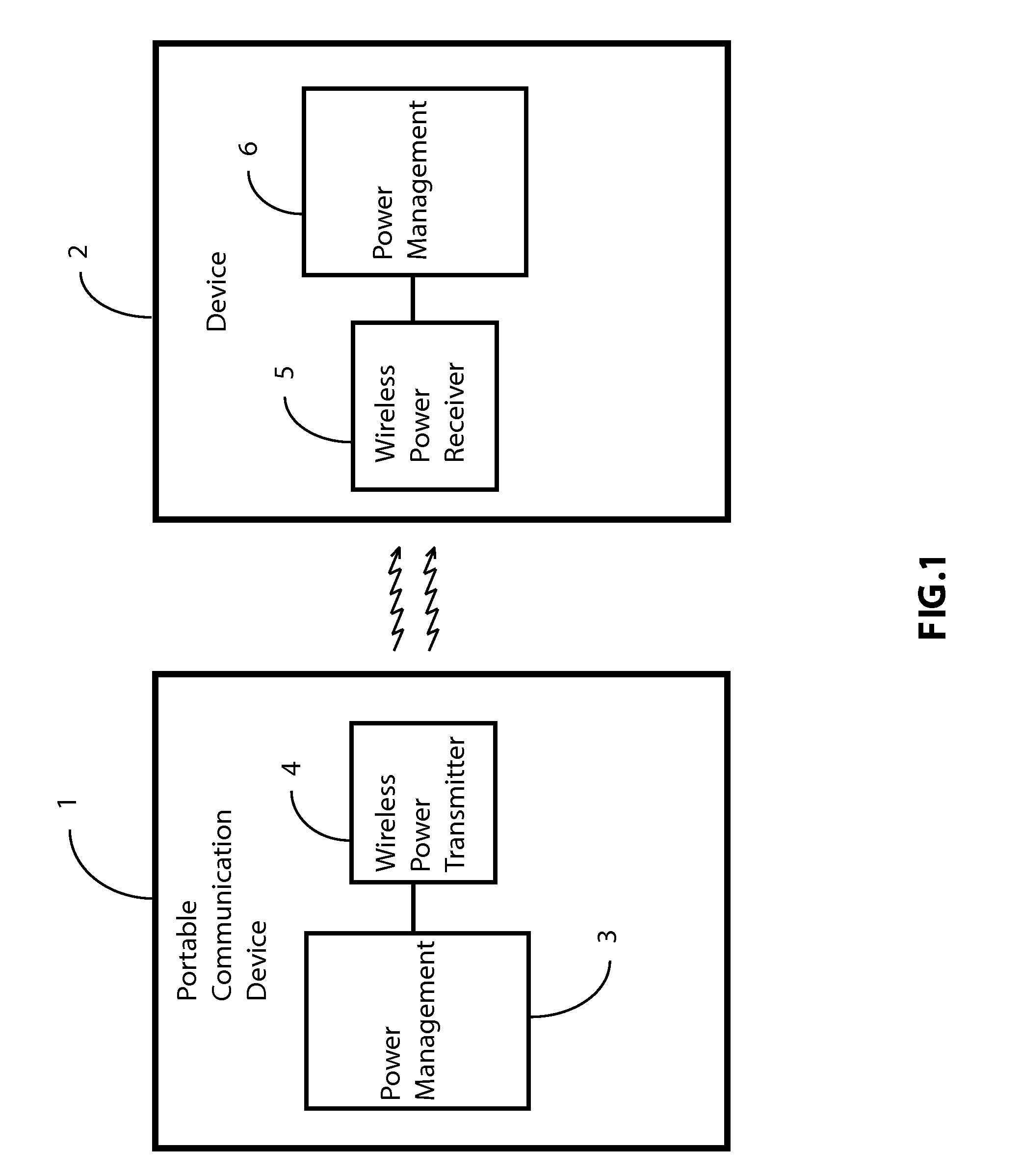
A FIG. 1

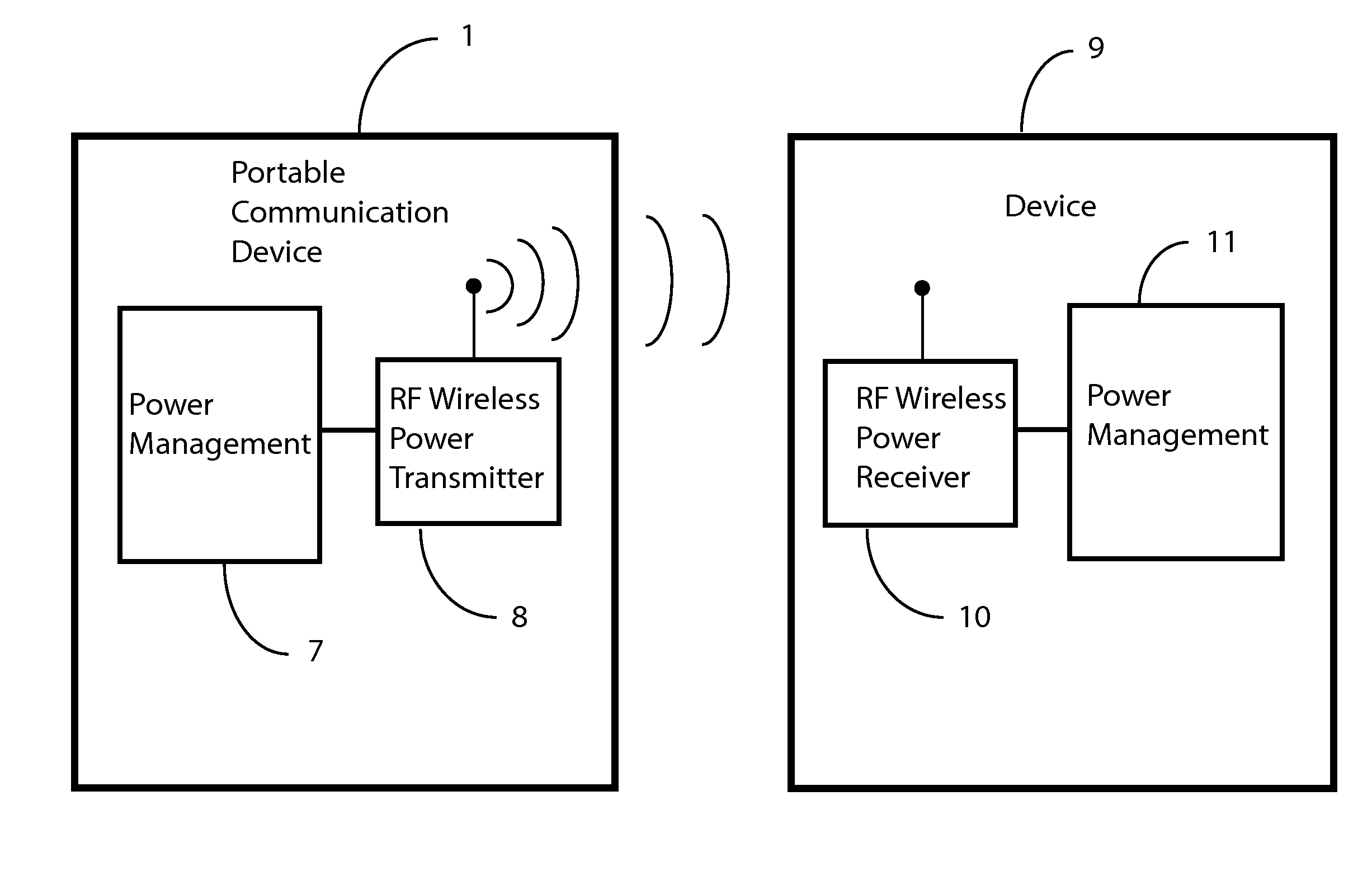
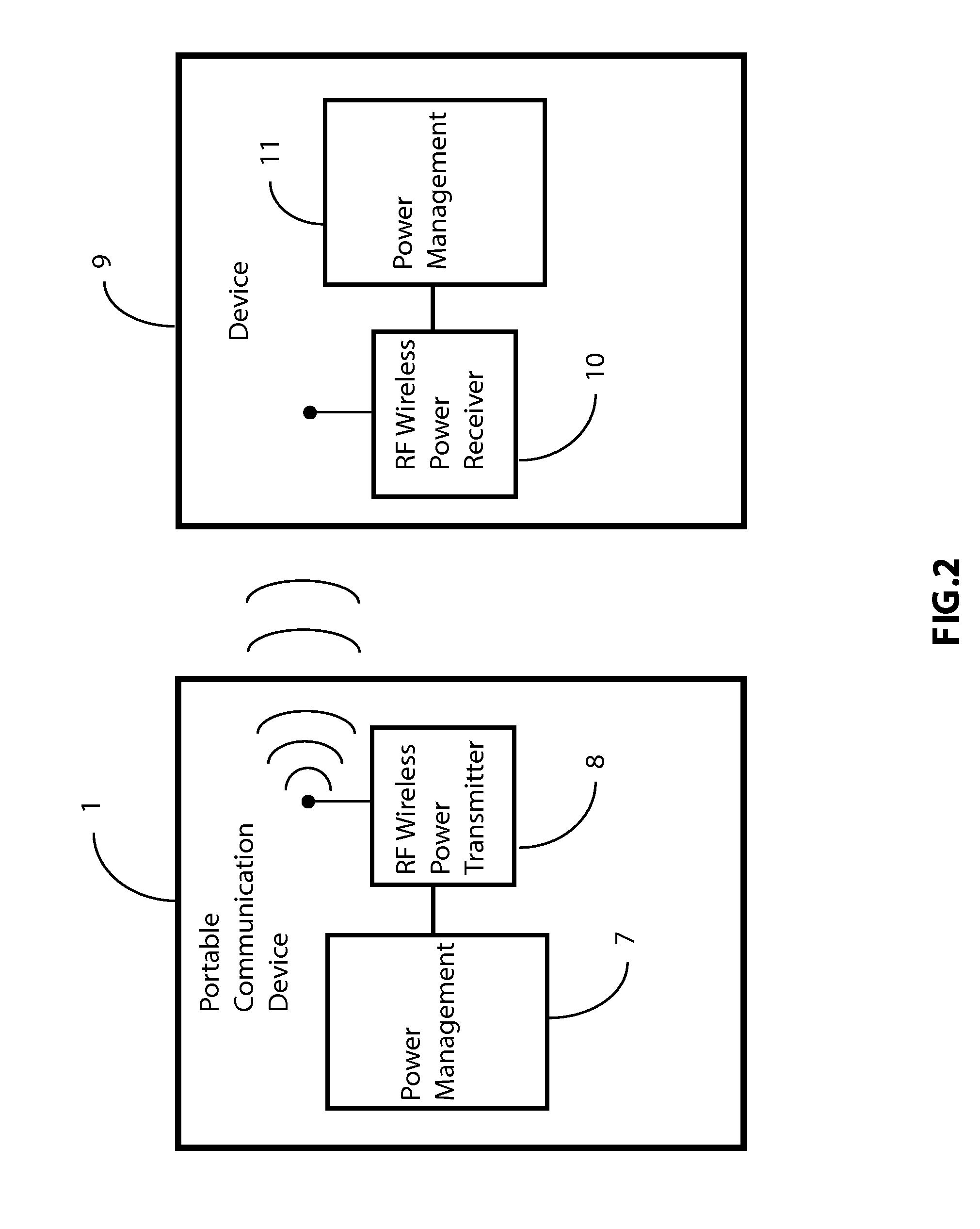
[0029]As shown in FIG. 1 a portable communication device 1 (mobile telephone or tablet), according to one general embodiment of the present invention, includes a wireless power transmitter 4 to transmit power to an external general device 2 which will comprise a wireless power receiver 5. A power management unit 3 in the cellular telephone may include the battery and devices to efficiently manage power to be transmitted and likewise in the external device the power received from the receiver is passed to a power management block 6 that may include circuits to convert the power to electric power, and a battery charger or direct means for utilizing the power received.

[0030]In particular, the use of a cellular telephone or tablet or telephone watch to wirelessly transmit power, makes the software for the utilization of the energy provider easy to program as an application of the telephone. It can be run simultaneously to other features of the portable telephones. The inherent p...


PUM


Abstract

The present invention describes means to intentionally transmit power wirelessly from a portable communication device like a mobile phone, smart-phone, tablet or telephone watch using radio frequency, ultrasound, microwave or laser technologies to power up or charge devices external to the portable communication device. In particular the wireless power transmitter is physically placed inside the portable communication device or coupled to it, in order to have a means to transfer power without wires or cables to other devices. The present invention may be utilized in applications like sensors, implanted devices for medical use, speakers, mouse, keyboard, electrical glasses for 3D viewing, small displays, gadgets in the car, electronic toys and so on.

Description

RELATED APPLICATION DATA[0001]The present application claims priority from U.S. Provisional Patent Application No. 61 / 733,860 for “Wireless Power Transmission in Mobile Phones and Tablets” filed on Dec. 5, 2012.BACKGROUND OF THE INVENTION[0002]1. Field of the Invention[0003]The present invention is in the field of wireless power transfer. The present invention is further in the field of radio-frequency power transfer. The present invention is further in the field of ultrasound power transfer. The present invention is further in the field of wireless power transfer within mobile telephones and tablets. The implementation is not limited to a specific technology, and applies to either the invention as an individual component or to inclusion of the present invention within larger systems which may be combined into larger integrated circuits.[0004]2. Brief Description of Related Art[0005]With the proliferation of portable devices there is a growing demand for battery charging means that ...

Claims


Application Information

Patent Timeline
Patent Type & Authority Applications(United States)
IPC IPC(8): H02J17/00
CPCH02J17/00H02J50/30H02J50/20H02J50/15
Inventor MENEGOLI, PAOLO
Owner NIRVANALOG INC
Why Eureka
Try Eureka