Electrochemical device

a technology of electrochemical devices and electrodes, applied in the direction of hybrid capacitor terminals, electrolytic capacitors, final product manufacture, etc., can solve the problems of edlcs, need to be further thinned, and the structure of conventional electrochemical devices such as edlcs has a problem in generation of wrinkles, so as to achieve excellent bending resistance, effectively prevent bending, and improve the effect of bending resistan

Active Publication Date: 2015-04-16
TDK CORPARATION
View PDF3 Cites 9 Cited by
  • Summary
  • Abstract
  • Description
  • Claims
  • Application Information

AI Technical Summary

Benefits of technology

[0020]By having such a structure, the electrochemical device can be further downsized with excellent bending resistance.
[0021]Preferably, sealing tapes sandwiching the first lead terminal and the second lead terminal respectively are inserted between the peripheral edges of the exterior sheet and thermally sealed, in order that the seal part is partially formed. Preferably, a width of the seal part corresponding to a length of the sealing tape is 1 mm or more. The larger the width of this seal part is, the more effective the measure of the electrolyte solution is, and bending resistance of the device is then improved.
[0022]Preferably, the electrochemical device further comprises a support sheet which prevents bending of the first lead terminal and the second lead terminal drawn from the seal part. By having such a structure, the first lead terminal and the second lead terminal which are drawn from the seal part can be effectively prevented from bending.
[0023]Preferably, the support sheet is formed by outwardly extending a part of a peripheral edge of the exterior sheet located at the seal part. By having such a structure, the support sheet can be easily formed.
[0024]Preferably, a protruding length of the support sheet is longer than that of the first lead terminal and the second lead terminal. By having such a structure, the first lead terminal and the second lead terminal which are drawn from the seal part can be effectively prevented from bending.

Problems solved by technology

However, conventional electrochemical devices have a thickness of 1 mm or larger, and thus they do not cope with bending.
However, in order to insert the conventional electrochemical devices into IC cards or so, they need to be further thinned.
On the other hand, structures of the conventional electrochemical devices such as EDLCs have a problem in generation of wrinkles at the time of bending.
Also, the conventional electrochemical devices particularly have a problem that wrinkles are easily generated on a space between a seal part of product peripheral edge and inner elements.

Method used


Image

  • Electrochemical device
  • Electrochemical device
  • Electrochemical device

Examples


first embodiment

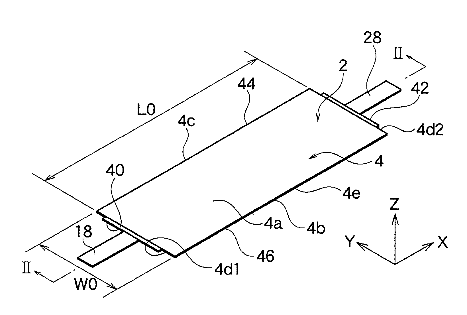
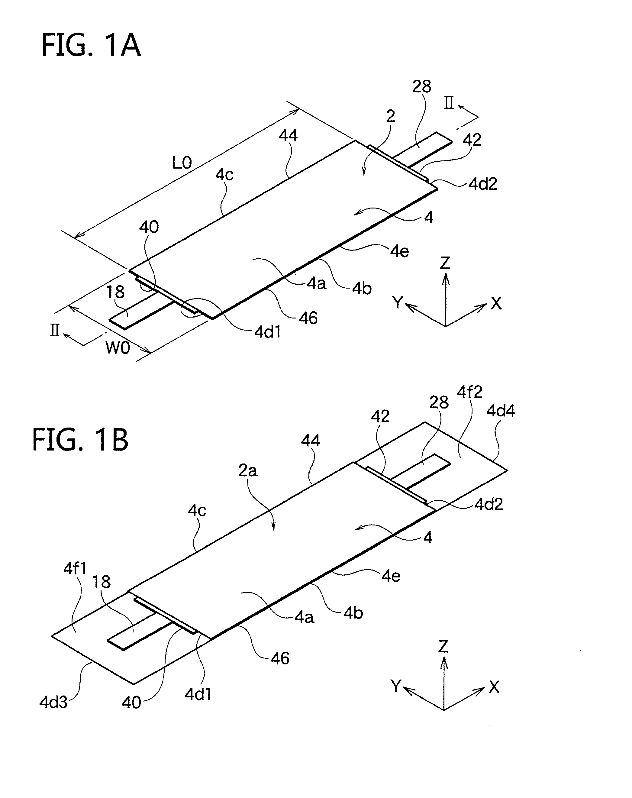
[0037]As shown in FIG. 1A, an electric double-layered capacitor (EDLC) 2 as an electrochemical device according to one embodiment of the present invention has an exterior sheet 4. A surface 4a and a rear surface 4b are formed on the exterior sheet 4 by folding the single sheet 4 and bending it at a peripheral edge 4c.

[0038]In the present embodiment, the exterior sheet 4 has a rectangular shape whose length L0 in the X-axis direction is longer than the length W0 in the Y-axis direction. However, the present invention is not limited to this, and the exterior sheet 4 may have a square, other polygonal, circular, elliptic, or other shape. In this embodiment, it is considered that a direction where the surface 4a and the rear surface 4b of the exterior sheet 4 overlap is a thickness direction (Z-axis direction), and that directions perpendicular to one another are the X-axis and the Y-axis, respectively.

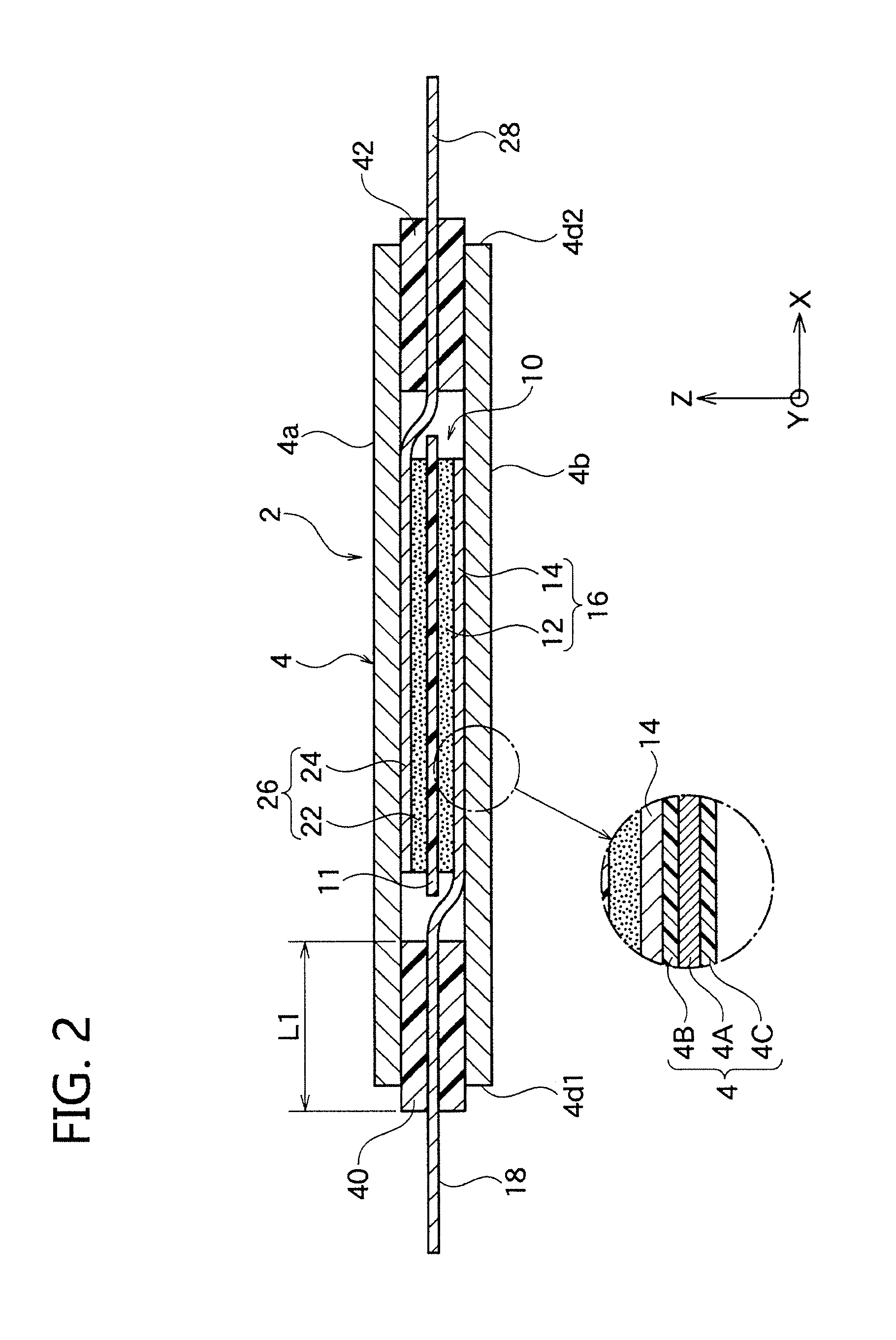
[0039]As described below with FIG. 2, an element body 10 is included in the exterior...

second embodiment

[0083]As shown in FIG. 1B, the EDLC 2 of the present embodiment further has support sheets 4f1 and 4f2, which prevent bending of a first lead terminal 18 drawn from the first seal part 40 and a second lead terminal 28 drawn from the second seal part 42. The others are the same as the first embodiment. Thus, the same numbers are distributed to common members in the drawings, and in the following explanation, common members will not be explained partially and different members will be explained in detail.

[0084]In the above-mentioned the first embodiment, as shown in FIG. 2, with respect to the peripheral edge 4d1 at the first seal part side of the exterior sheet 4, the surface 4a and the rear surface 4b of the exterior sheet 4 are located at the same position in the X-axis direction. On the other hand, in the present embodiment, as shown in FIG. 1B, the support sheet 4f1 is formed by extending the peripheral edge 4d3 of the exterior sheet 4, which is located on the rear surface 4b of ...

third embodiment

[0088]As shown in FIG. 7, in an EDLC 2b of the present embodiment, two element bodies 10a and 10b are included in the exterior sheet 4 in line with the Y-axis direction. The others are the same as the first embodiment. Thus, the same numbers are distributed to common members in the drawings, and in the following explanation, common members will not be explained partially and different members will be explained in detail.

[0089]In the present embodiment, as shown in FIG. 7, the exterior sheet 4 is provided with a surface sheet 4a1 and a rear surface sheet 4b1 and has an approximately double size in the Y-axis direction compared with the exterior sheet 4 shown in FIG. 1A. As shown in FIG. 8, the two element bodies 10a and 10b are included in the exterior sheet 4, and the separator layer 11 is shared by the two element bodies 10a and 10b. The element bodies 10a and 10b respectively have the same structure as the element body 10 of the first embodiment except that the separator layer 11 ...


PUM


Abstract

An electrochemical device comprises an element body 10 in which a pair of a first inner electrode and a second inner electrode are laminated to sandwich a separator layer; an exterior sheet 4 covering the element body; a first lead terminal 18 drawn to an outside of the exterior sheet 4; and a second lead terminal 28 drawn to the outside of the exterior sheet 4. A proof stress of the exterior sheet is 390 to 980 N/mm2 in JIS Z2241, and a hardness of the exterior sheet is 230 to 380 Hv in Vickers hardness (JIS Z2244).

Description

BACKGROUND OF THE INVENTION[0001]1. Field of the Invention[0002]The present invention relates to an electrochemical device preferably used as an electric double-layered capacitor (EDLC) and the like. In more detail, the present invention relates to the electrochemical device enabling thinning and further having excellence in bending resistance.[0003]2. Description of the Related Art[0004]Recently, the spread of IC cards loading IC chips is really astonishing. Especially, there are IC cards allowing transfer of money, and IC cards are used for various usage such as employee IDs or membership cards. In the future, further measures addressing high functionalization thereof are being required.[0005]Thus, IC cards using secondary batteries need to be developed. However, conventional electrochemical devices have a thickness of 1 mm or larger, and thus they do not cope with bending. Then, as shown in such as Patent Document 1, the electrochemical devices for thinning are proposed.[0006]How...

Claims


Application Information

Patent Timeline
Patent Type & Authority Applications(United States)
IPC IPC(8): H01G11/80H01G11/58H01G11/74H01G11/52H01G11/26
CPCH01G11/80H01G11/52H01G11/26H01G11/74H01G11/58H01G11/82Y02P70/50Y02E60/13
Inventor SAYA, YUKO
Owner TDK CORPARATION
Why Eureka
Try Eureka