
Turbine rotor blades with improved tip portion cooling holes

a technology of turbine rotor blades and cooling holes, which is applied in the direction of sustainable transportation, mechanical equipment, machines/engines, etc., can solve the problem of cooling remaining a challeng

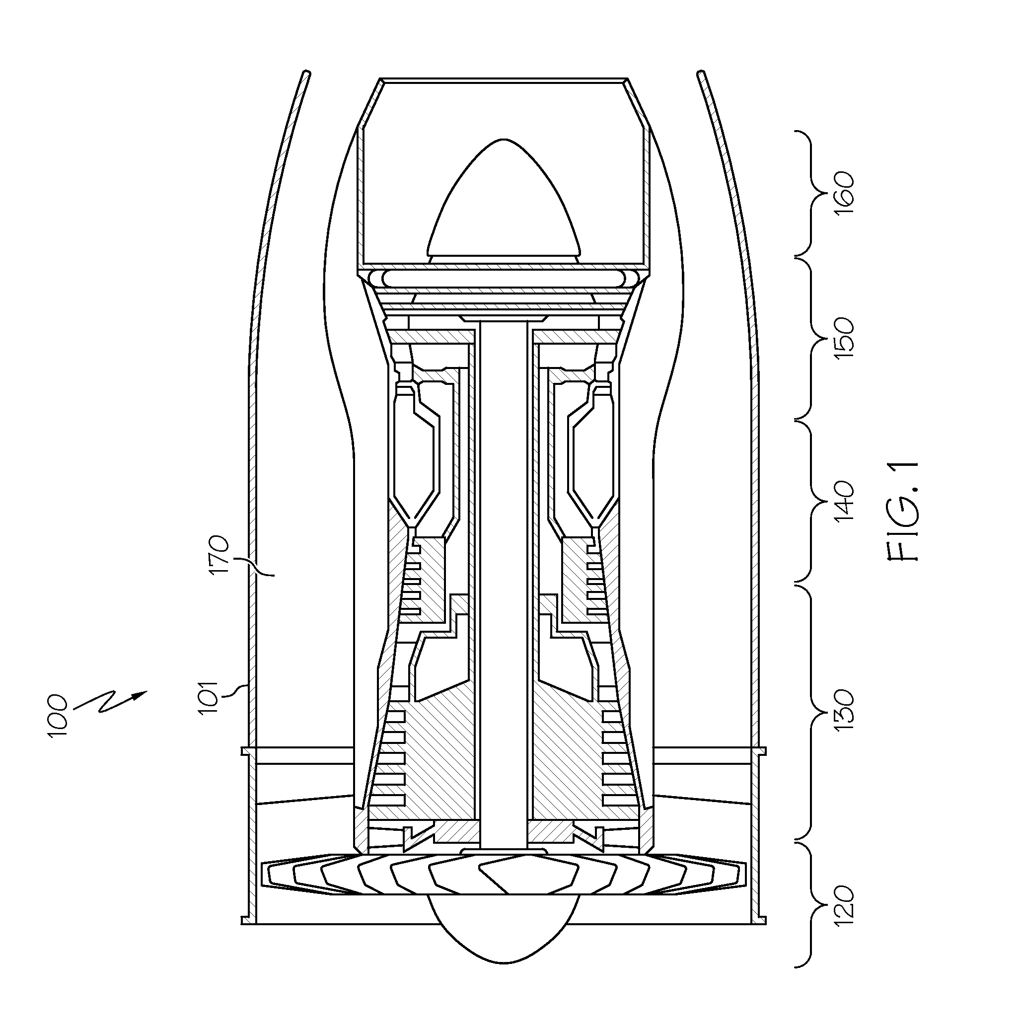
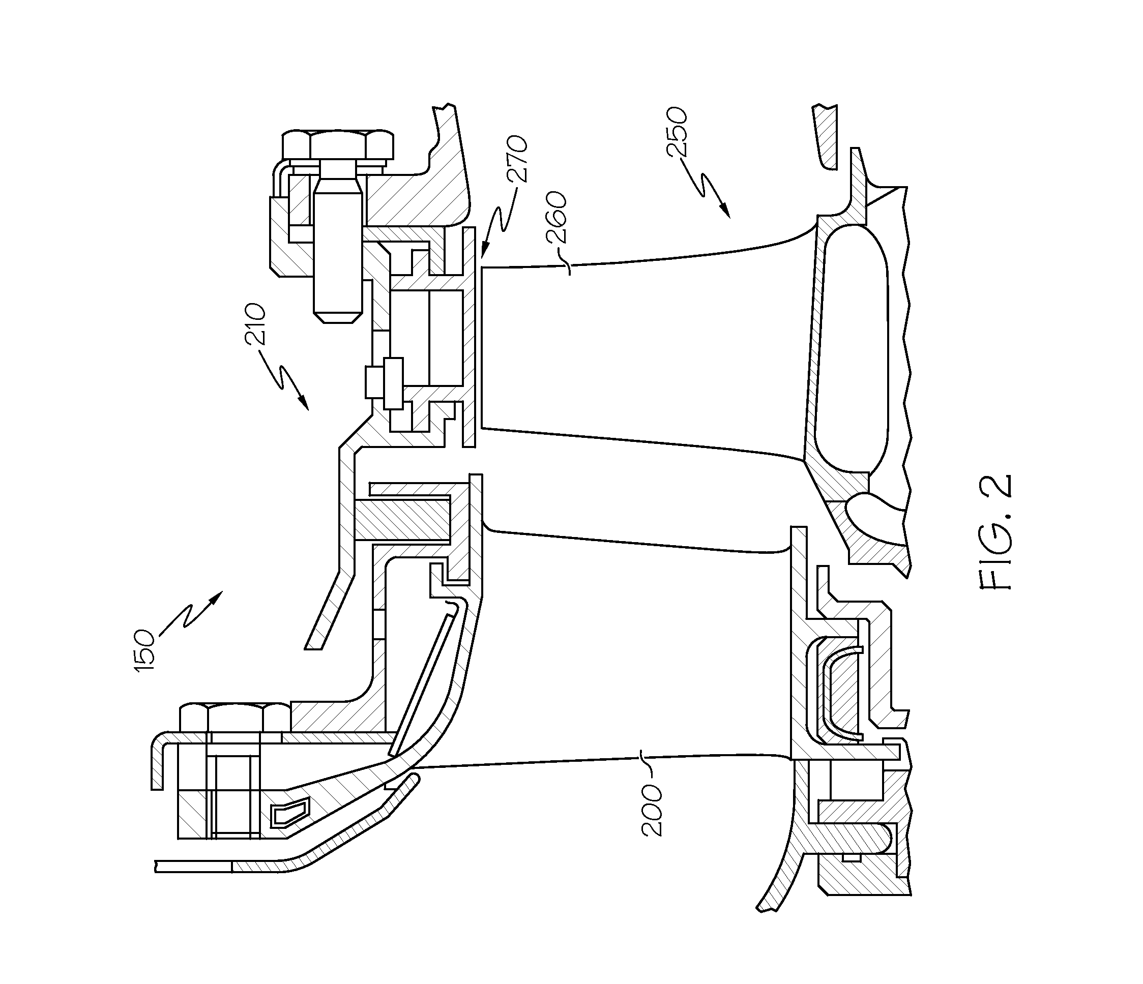
Active Publication Date: 2015-04-16
HONEYWELL INT INC
View PDF7 Cites 18 Cited by
  • Summary
  • Abstract
  • Description
  • Claims
  • Application Information

AI Technical Summary

Benefits of technology

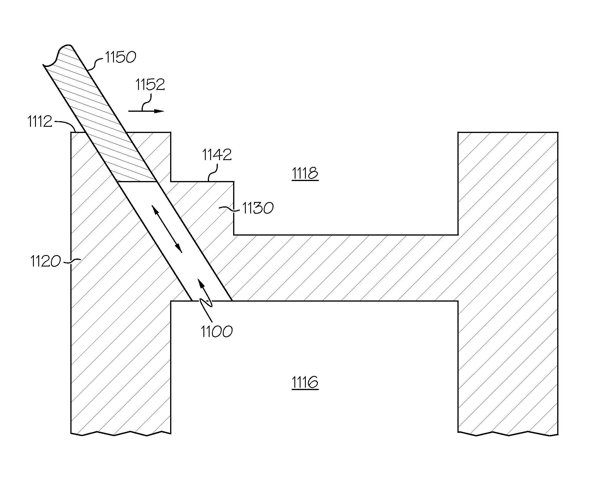
This patent describes a turbine rotor blade with a cooling system that helps to prolong the life of the blades. The blade has an airfoil with multiple walls and a cooling hole that delivers cooling air to the blade. The cooling hole has a closed channel and an open channel which form a slot. The method for manufacturing the blade involves forming the blade with the airfoil and cooling channel, creating a step between the two walls, and then using a tool to remove material and create the cooling hole. The technical effect of this invention is a more efficient and effective cooling system for turbine rotor blades, which can improve engine performance and durability.

Problems solved by technology

However, given the high temperature of engine operation, cooling remains a challenge, particularly in areas such as the turbine blade tips.

Method used


Image

  • Turbine rotor blades with improved tip portion cooling holes
  • Turbine rotor blades with improved tip portion cooling holes
  • Turbine rotor blades with improved tip portion cooling holes

Examples


Embodiment Construction

[0020]The following detailed description is merely exemplary in nature and is not intended to limit the inventive subject matter or the application and uses of the inventive subject matter. Furthermore, there is no intention to be bound by any theory presented in the preceding background or the following detailed description.

[0021]Exemplary embodiments discussed herein are directed to turbine rotor blades capable of withstanding temperature environments that are higher than those for which conventional turbine rotor blades are designed. Generally, the improved turbine rotor blade includes a first parapet wall extending from the first side wall including a first tip edge, a second parapet wall extending from the second side wall opposite the first side wall and including a second tip edge, and a tip wall extending between the first side wall and the second side wall. To provide improved cooling, the turbine blade further includes a step formed between the first tip edge and the tip c...


PUM

PropertyMeasurementUnit
heightaaaaaaaaaa
heightaaaaaaaaaa
angleaaaaaaaaaa

Abstract

A turbine rotor blade is provided for a turbine section of an engine. The turbine rotor blade includes a platform and an airfoil extending from the platform into a mainstream gas path of the turbine section. The airfoil includes a first side wall; a second side wall joined to the first side wall at a leading edge and a trailing edge; a tip cap extending between the first side wall and the second side wall; a first parapet wall extending from the first side wall; and a first cooling hole through the tip cap and the first parapet wall configured to deliver cooling air. The first cooling hole has a closed channel section and an open channel section. The open channel section forms a slot.

Description

STATEMENT REGARDING FEDERALLY SPONSORED RESEARCH OR DEVELOPMENT[0001]This invention was made with Government support under DTFAWA-10-C-00040 awarded by Federal Aviation Administration. The Government has certain rights in this invention.TECHNICAL FIELD[0002]The inventive subject matter generally relates to turbine rotor blades, and more particularly relates to turbine rotor blades with tip portion cooling holes.BACKGROUND[0003]Gas turbine engines are generally used in a wide range of applications, such as aircraft engines and auxiliary power units. In a gas turbine engine, air is compressed in a compressor, mixed with fuel, and ignited in a combustor to generate hot combustion gases, which flow downstream into a turbine section. In a typical configuration, the turbine section includes rows of airfoils, such as stator vanes and rotor blades, disposed in an alternating sequence along the axial length of a generally annular hot gas flow path. The rotor blades are mounted at the periphe...

Claims


Application Information

Patent Timeline
Patent Type & Authority Applications(United States)
IPC IPC(8): F01D5/18F01D5/14
CPCF01D5/18F01D5/147F05D2230/00F05D2260/20F01D5/20Y10T29/49341Y02T50/60
Inventor WALDMAN, DAVIDMORRIS, MARK C.MALAK, MALAK FOUAD
Owner HONEYWELL INT INC
Learn More