Substrate processing apparatus and substrate processing method

Active Publication Date: 2015-04-16
EBARA CORP
View PDF4 Cites 6 Cited by
  • Summary
  • Abstract
  • Description
  • Claims
  • Application Information

AI Technical Summary

Benefits of technology

[0005]According to embodiments, there are provided a substrate processing apparatus and a substrate processing method capable of accurately aligning a center of a substrate, such as

Problems solved by technology

However, such a conventional centering mechanism has a limit to an accuracy of the wafer centering.
As a result, the polishing w

Method used


Image

  • Substrate processing apparatus and substrate processing method
  • Substrate processing apparatus and substrate processing method
  • Substrate processing apparatus and substrate processing method

Examples


Embodiment Construction

[0027]Embodiments will be described below with reference to drawings. The following embodiments of a substrate processing apparatus and a substrate processing method are directed to a polishing apparatus and a polishing method for polishing a peripheral portion of a substrate.

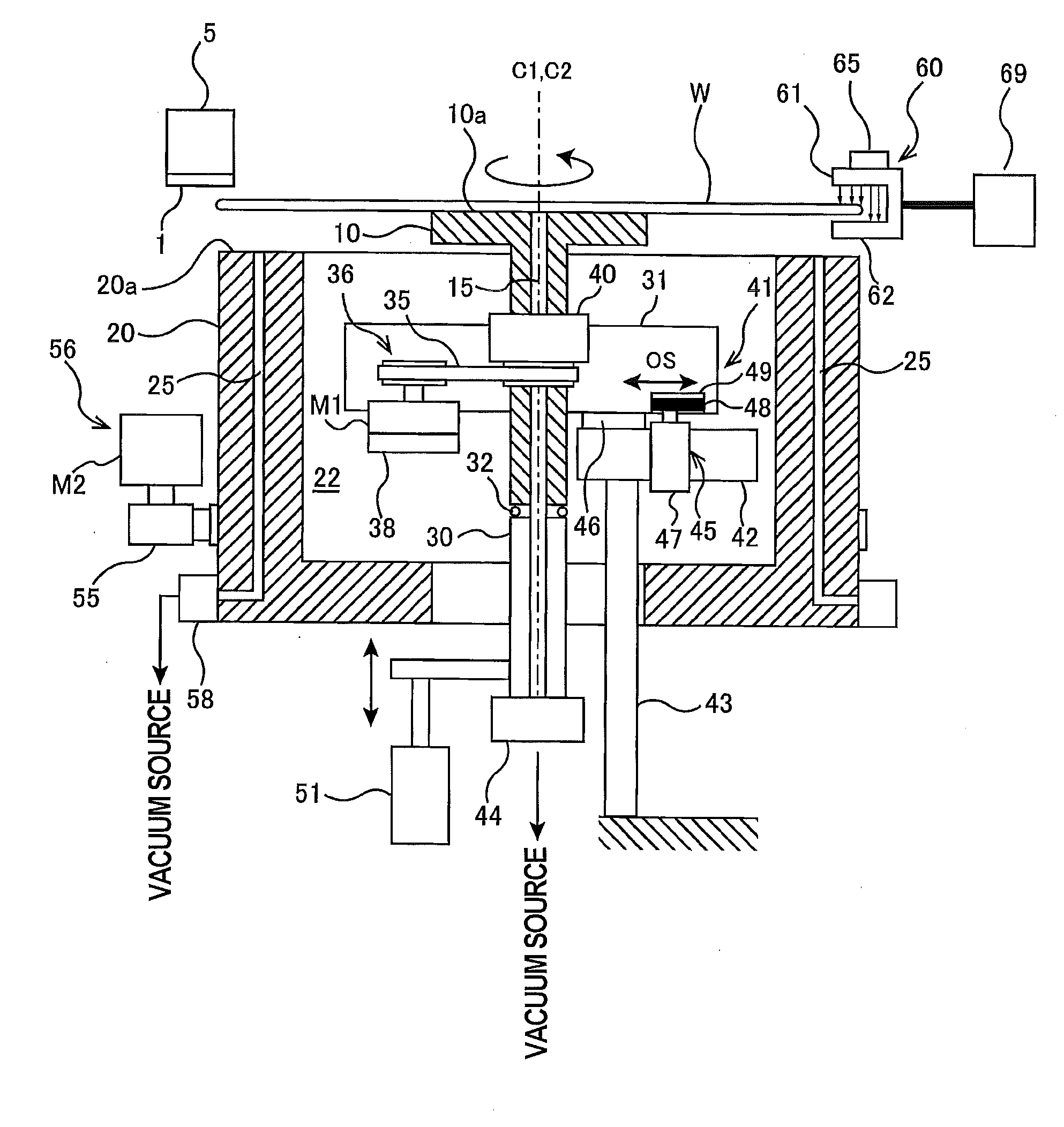
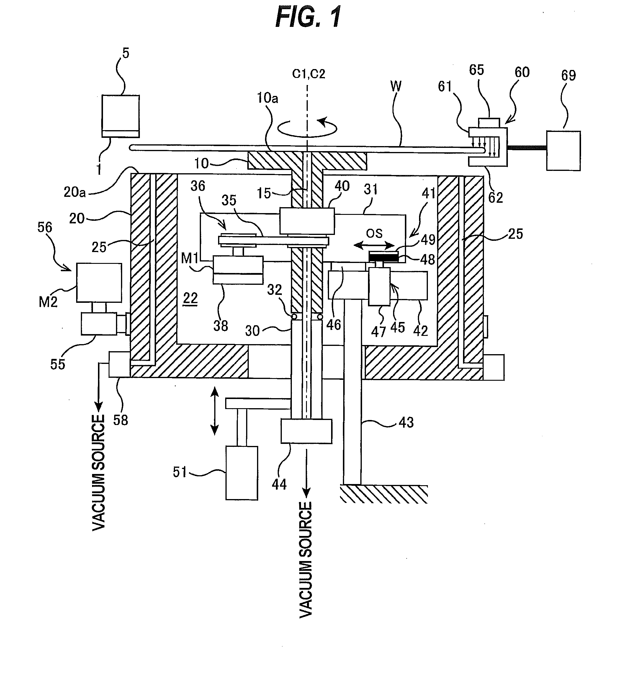
[0028]FIG. 1 is a schematic view showing the polishing apparatus, As shown in FIG. 1, the polishing apparatus has a first substrate stage 10 and a second substrate stage 20 each for holding the wafer W which is an example of a substrate. The first substrate stage 10 is a centering stage for performing centering of the wafer W, and the second substrate stage 20 is a process stage for polishing the wafer W. During centering of the wafer W, the wafer W is held by only the first substrate stage 10, and during polishing of the wafer W, the wafer W is held by only the second substrate stage 20.

[0029]The second substrate stage 20 has a space 22 formed therein, and the first substrate stage 10 is housed in the space 22...


PUM

PropertyMeasurementUnit
Diameteraaaaaaaaaa
Vacuumaaaaaaaaaa

Abstract

A substrate processing apparatus capable of accurately aligning a center of a substrate, such as a wafer, with an axis of a substrate stage and capable of processing the substrate without bending the substrate is disclosed. The substrate processing apparatus includes a first substrate stage having a first substrate-holding surface configured to hold a first region in a lower surface of the substrate, a second substrate stage having a second substrate-holding surface configured to hold a second region in the lower surface of the substrate, a stage elevator configured to move the first substrate-holding surface between an elevated position higher than the second substrate-holding surface and a lowered position lower than the second substrate-holding surface, and an aligner configured to measure an amount of eccentricity of a center of the substrate from the axis of the second substrate stage and align the center of the substrate with the axis of the second substrate stage.

Description

CROSS REFERENCE TO RELATED APPLICATION[0001]This document claims priority to Japanese Application Number 2013-213489, filed Oct. 11, 2013, the entire contents of which are hereby incorporated by reference.BACKGROUND[0002]A polishing apparatus provided with a polishing tool, such as a polishing tape or a grinding stone, is used as an apparatus for polishing a peripheral portion of a substrate, such as a wafer. FIG. 14 is a schematic view showing this type of polishing apparatus, As shown in FIG. 14, the polishing apparatus includes a substrate stage 110 for holding a central portion of a wafer W by vacuum suction and rotating the wafer W, and a polishing head 105 for pressing a polishing tool 100 against a peripheral portion of the wafer W. The wafer W is rotated together with the substrate stage 110, and in this state the polishing head 105 presses the polishing tool 100 against the peripheral portion of the wafer W to thereby polish the peripheral portion of the wafer W. A polishin...

Claims


Application Information

Patent Timeline
IPC IPC(8): B24B37/34B24B37/30B24B37/10
CPCB24B37/345B24B37/10B24B37/30B24B37/005B24B49/12
Inventor SEKI, MASAYATOGAWA, TETSUJINAKANISHI, MASAYUKIITO, KENYA
Owner EBARA CORP
Why Eureka
Try Eureka