Harmonic Drive Gear Reduction Mechanism

a gear reduction and gear technology, applied in the direction of gears, belts/chains/gears, mechanical instruments, etc., can solve the problem of limited structural strength of wave generators, achieve the effect of reducing the pitch error of each tooth, increasing the number of engaged teeth, and enhancing transmission accuracy

Active Publication Date: 2015-04-23
HIWIN TECH
View PDF5 Cites 22 Cited by
  • Summary
  • Abstract
  • Description
  • Claims
  • Application Information

AI Technical Summary

Benefits of technology

[0011]The primary objective of the present invention is to provide a harmonic drive gear reduction mechanism capable of increasing the number of engaged teeth, reducing pitch error for each tooth, and enhancing transmission accuracy.

Problems solved by technology

However, the angle a for the arc-shaped section which has the radius R1 is only 5 degrees, therefore, the structural strength of the wave generator is limited.

Method used


Image

  • Harmonic Drive Gear Reduction Mechanism
  • Harmonic Drive Gear Reduction Mechanism
  • Harmonic Drive Gear Reduction Mechanism

Examples


Embodiment Construction

[0038]The present invention will be clearer from the following description when viewed together with the accompanying drawings, which show, for purpose of illustrations only, the preferred embodiment in accordance with the present invention.

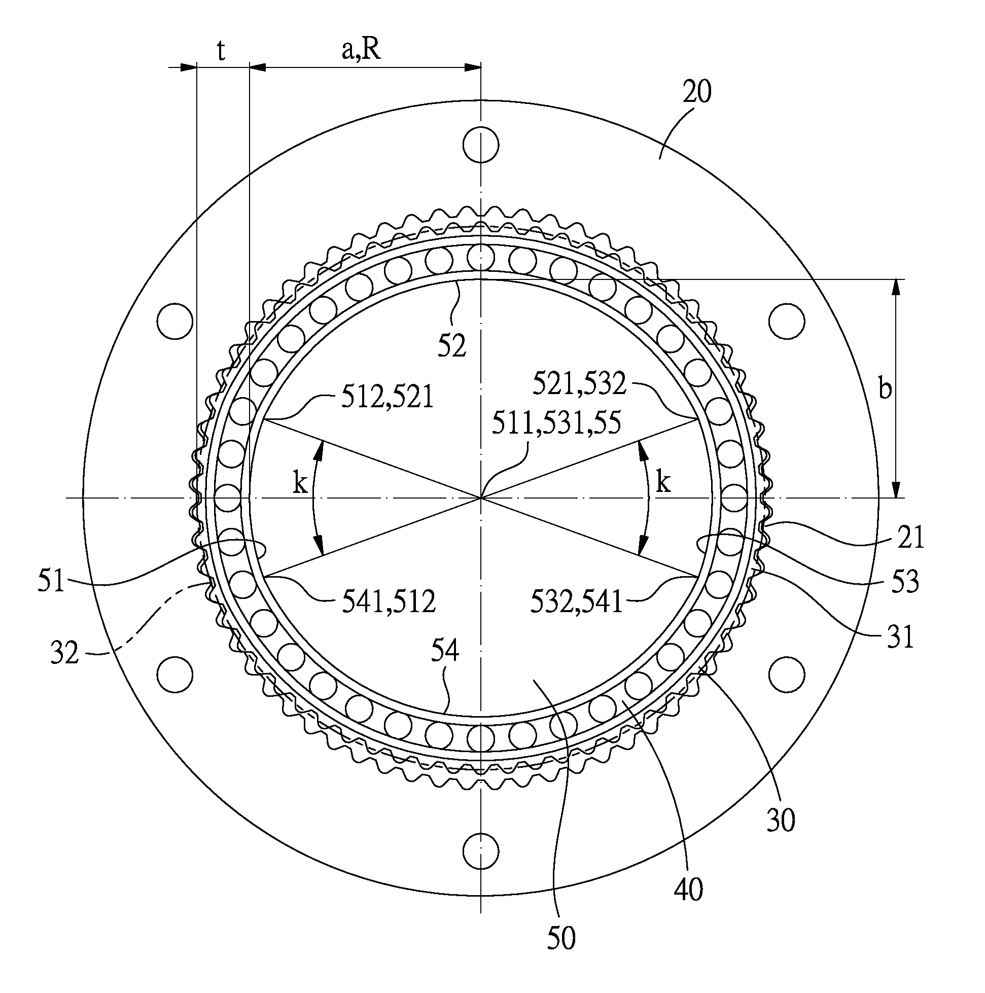
[0039]Referring to FIG. 14A, a harmonic drive gear reduction mechanism in accordance with a first embodiment of the present invention comprises: a rigid inner spline 20, a flexible outer spline 30, a flexible bearing 40 and a wave generator 50.

[0040]The rigid inner spline 20 is a hollow circular structure provided with 2(n+1) teeth and has a tooth module of m. In this embodiment, the teeth of the rigid inner spline 20 are involute teeth.

[0041]The flexible outer spline 30 is a hollow circular structure inserted in the rigid inner spline 20 and provided with 2n teeth and the same tooth module of m as the rigid inner spline 20. In this embodiment, the teeth of the flexible outer spline 30 are involute teeth, and in a valid area, the rigid inner spli...


PUM


Abstract

A harmonic drive gear reduction mechanism includes a rigid inner spline with 2(n+1) teeth and a tooth module of m, a flexible outer spline inserted in the rigid inner spline has 2n teeth and a tooth module of m, a flexible bearing inserted in the flexible outer spline, and a wave generator inserted in the flexible bearing. A thickness between an inner diameter of the flexible bearing and a pitch diameter of the flexible outer spline is t, a cross sectional profile of the wave generator consists four curves, the first and third curves have a radius of curvature R, R=m (n+1)−t, a central angle of the first and third curves is k, and 10<k≦60, the second and fourth curves and conjunction points between the second, fourth curves and the first, third curves can be first-order differentiated.

Description

BACKGROUND OF THE INVENTION[0001]1. Field of the Invention[0002]The present invention relates to a gear reduction mechanism, and more particularly to a harmonic drive gear reduction mechanism.[0003]2. Description of the Prior Art[0004]FIG. 1 shows a conventional harmonic drive gear reduction mechanism disclosed in U.S. Pat. No. 7,178,427 B, which comprises a rigid inner spline 11, a flexible outer spline 12 disposed in the rigid inner spline 11, a flexible bearing 13 disposed in the flexible outer spline 12, and a wave generator 14 disposed in the flexible bearing 13. When the wave generator 14 rotates, it pushes against and makes the flexible bearing 13 and the flexible outer spline 12 deform, and as a result, the teeth at different parts of the deformed flexible outer spline 12 will be engaged with the teeth of corresponding part of the rigid inner spline 11, furthermore, the flexible outer spline 12 has less teeth than the rigid inner spline 11, so that a rotation speed reduction...

Claims


Application Information

Patent Timeline
Patent Type & Authority Applications(United States)
IPC IPC(8): F16H49/00
CPCF16H49/001F16H2049/003Y10T74/19642
Inventor KUO, CHANG-HSIN
Owner HIWIN TECH
Why Eureka
Try Eureka