
Poppet Valve Assembly With In-Line Sight Glass

Inactive Publication Date: 2015-04-23
DIXON VALVE & COUPLING COMPANY
View PDF15 Cites 2 Cited by
  • Summary
  • Abstract
  • Description
  • Claims
  • Application Information

AI Technical Summary

Benefits of technology

This patent describes a device called a poppet valve assembly that has a sight glass mounted inside it. The sight glass is made of see-through material, like acrylic or glass, and is held in place by a retainer. The sight glass is positioned in line with the flow of fluid inside the valve and has an opening that is connected to the flow. The size and shape of the cut-outs in the housing make it easy for a truck operator to determine if fluid is present and what type of fluid it is, from a distance. This helps prevent accidental spills or damage to the environment or the operator. The invention is designed to be cost-effective and easy to use.

Problems solved by technology

As this happens, any liquid present in the poppet valve assembly will be released and may spill on the driver.
One disadvantage with using this type of in-line sight glass is that the sight glass is highly stressed by the bolts that attach it to the mounting flange of a discharge pipe of a truck.
The result is that the sight glass has a short lifespan and must be replaced often.
Due to the large size of such a sight glass, repair is costly and may remove the tanker truck from operation for a lengthy period of time.
One disadvantage with using this type of in-line sight glass is that, from a distance, it may be difficult to view the interior of the poppet valve assembly.
Therefore, it will be difficult to determine if fluid is present.
Another disadvantage with using this type of in-line sight glass assembly is the high cost of the sight glass assembly due to its multiple components and required assembly.
Each of these methods requires securing an element or elements between the mounting flange of the discharge pipe on the truck and the mounting flange of a poppet valve assembly, thereby increasing the chance of leaks or spills while increasing the cost of assembly, i.e., more labor.

Method used


Image

  • Poppet Valve Assembly With In-Line Sight Glass
  • Poppet Valve Assembly With In-Line Sight Glass
  • Poppet Valve Assembly With In-Line Sight Glass

Examples


Embodiment Construction

[0027]Referring to the figures, and particularly FIG. 3, there is illustrated a fuel tanker truck 10 having a tank 11 with four compartments 12a, 12b, 12c, and 12d having respective covers 14a, 14b, 14c, and 14d. Although the compartments are illustrated by dashed lines, these dashed lines are for illustration purposes only. The truck may have any number of compartments in any location. Below the tank 11 are a plurality of pipes 16a, 16b, 16c, and 16d in fluid communication with the compartments 12a, 12b, 12c, and 12d, respectively. Each of the pipes 16a, 16b, 16c, and 16d has a poppet valve assembly 20 secured to a mounting flange at the end thereof, like the one disclosed in U.S. Pat. No. 7,896,027 to control the flow of fuel.

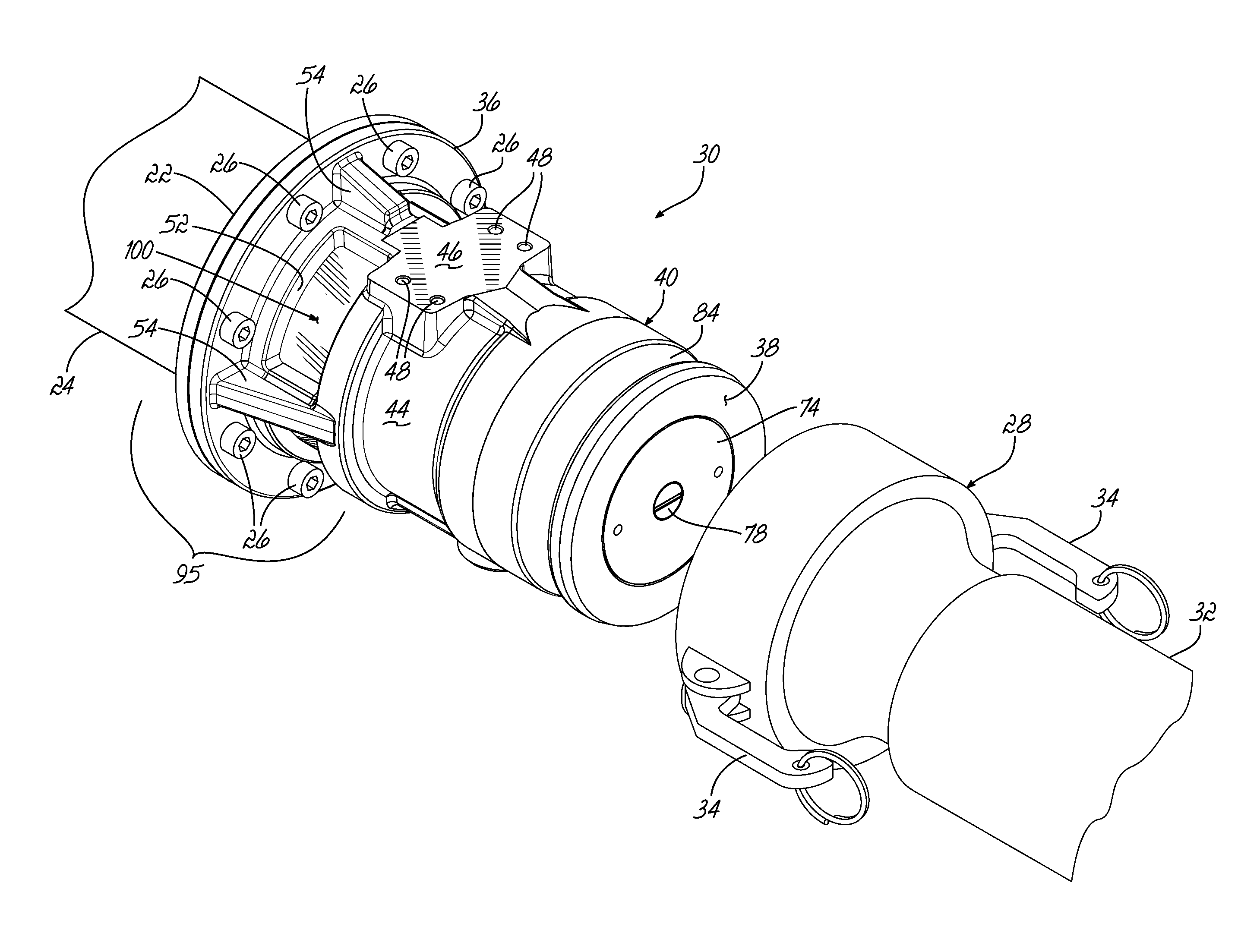
[0028]A different poppet valve assembly 30, the subject of the present invention, is secured to a mounting flange 22 located at the lower end of a vapor recovery pipe 24 to control the flow of fuel vapors or gases. As shown in FIG. 3, the vapor recovery pipe ...


PUM


Abstract

A poppet valve assembly is provided for use on a fuel tanker truck which enables the truck's driver to determine whether fuel is present in the valve assembly. The valve assembly has a housing which has a sight glass secured therein. The sight glass is visible through cut-outs in the housing. If the driver observes liquid in the valve assembly, the driver may drain the valve assembly to avoid spilling the liquid prior to opening the poppet valve assembly. When the poppet valve assembly is opened, vapor flows through a flow channel in the poppet valve assembly.

Description

FIELD OF THE INVENTION[0001]This invention relates generally to poppet valve assemblies for controlling flow therethrough of vapors, such as gasoline vapors, from a gasoline tank truck to a loading rack facility or from an underground storage tank at a filling station into a tank truck.BACKGROUND OF THE INVENTION[0002]In order to fill one or more underground storage tanks at a gasoline service station, a cargo tank truck typically pulls into the service station and unloads the fuel from the truck into the underground storage tank or tanks. Such a cargo tank truck commonly has multiple fuel storage compartments, each compartment having a cover and a pipe located below the tank to which is connected a valve assembly. The valve assembly is commonly a poppet valve assembly which is opened and closed by the truck's driver via a handle extending upwardly from the valve assembly, such as the poppet valve assembly disclosed in U.S. Pat. No. 7,896,027. In order to unload fuel from one of the...

Claims


Application Information

Patent Timeline
IPC IPC(8): F16K37/00
CPCF16K37/0058F16L37/16F16L37/18F16L37/40Y10T137/8359
Inventor FAHL, RICHARD L.
Owner DIXON VALVE & COUPLING COMPANY
Features
  • Generate Ideas
  • Intellectual Property
  • Life Sciences
  • Materials
  • Tech Scout
  • Unparalleled Data Quality
  • Higher Quality Content
  • 60% Fewer Hallucinations
Learn More